
Branchline mixer
Branchline Mixer Theory
The branchline mixer is simply a balanced mixer where the balun is replaced by the branchline coupler. For this design, you will use all four ports of the branchline, so you will want to remove any 50 Ohm termination you may have put on in you design for the fourth port.
The Branchline mixer is an RF down converting mixer that does not require any transformer or balun. The mixer is composed of three parts: 1) a branchline coupler to create a quadrature component of each input signal, the RF and LO, and to combine those two signals; 2) A diode with a nonlinear voltage to current transfer function (as all diodes have); and, 3) a low pass filter (LPF) to remove the RF and LO and leave only the intermediate frequency (IF). The branchline coupler, Fig. 3(a), splits the signals at the RF and LO ports into two signals with 90 degrees of phase shift. The RF is split into the two output ports, creating a sine and cosine version of the RF. Likewise, the LO is split into the two output ports and creates a sine and cosine version of the LO. Thus, at the terminals of each diode, there is a signal which is sin(RFt)+cos(LOt) or sin(LOt)+cos(RFt). A virtual ground exists at the junction of the two diodes. In each diode, the voltage to current transfer function is an exponential, which can be approximated by a Taylor series:
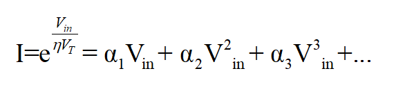 Eq. 5
Eq. 5
The mixer uses the square term to provide the “mixing” or multiplication. The square term will produce
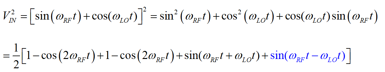 Eq. 6
Eq. 6
The last term (in blue) is our desired term. Note that all other powers of Vin in Eq. 5 will produce additional harmonics. The job of the mixer is to filter or cancel as many of these other unwanted harmonics as possible. From the first term, Vin will produce LO and RF signals in the diode and since 1 is typically the largest coefficient in a Taylor series, their contribution to the output signal will be significant. While a down converting mixer could filter them out, we can also cancel them by adding the current from two diodes whose voltages are opposite. The opposing polarity of the two diodes in the branchline mixer achieves this. Figure 3(c) shows the diode currents for a single and dual diode configuration. One can see that the dual diode significantly cancels the LO.
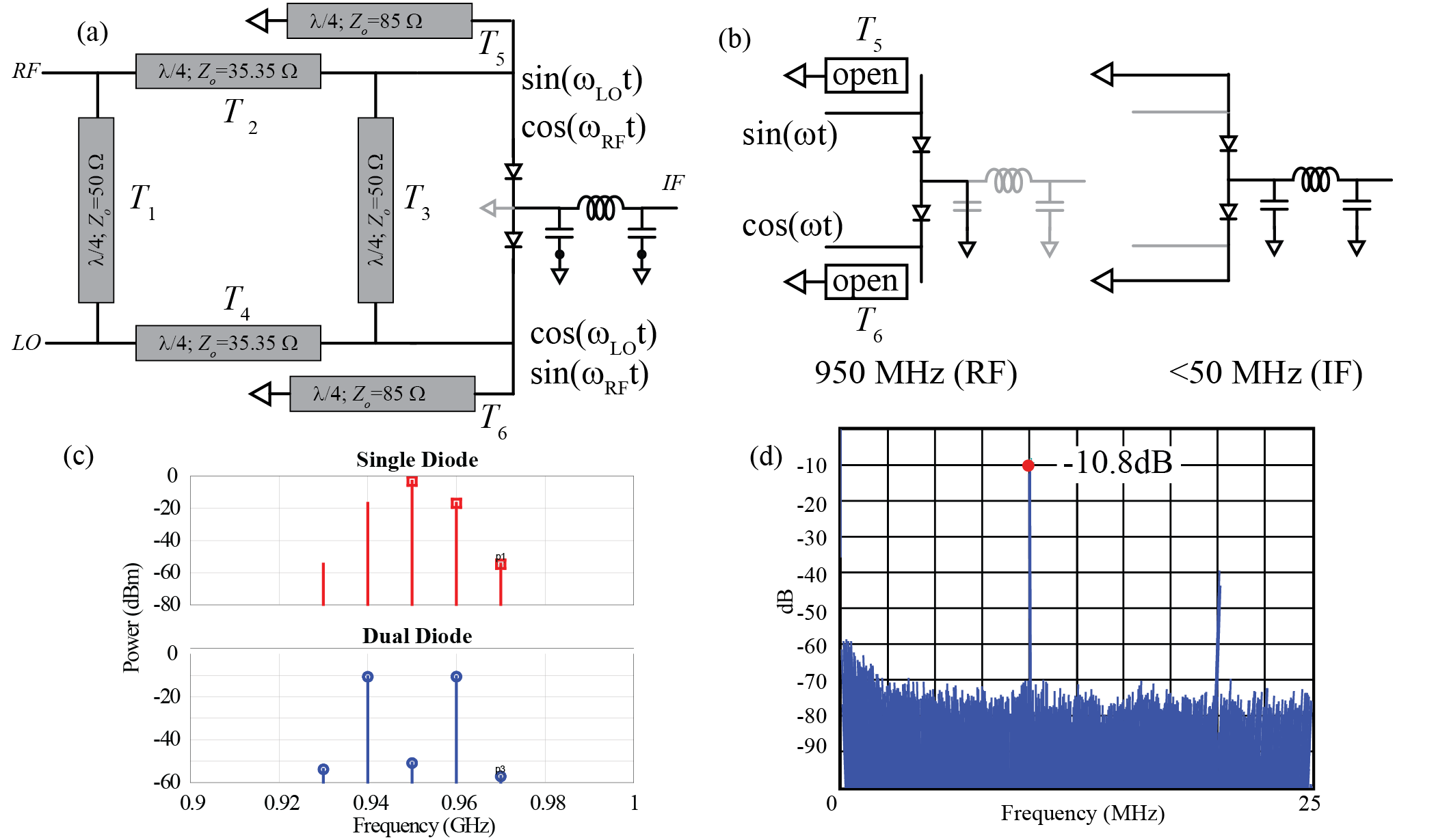 |
| Figure 3: (a) Branchline mixer. The branchline consists of four /4 sections, with the top and bottom at 35 and the left and right at 50 [2]. The Branchline separates each input into two outputs with a 90-degree phase shift. Two /4 sections are added to provide a DC path to ground for the mixer, but are open at RF. (b) Shows operation at RF and IF frequencies, where black indicates the active components/paths. (c) Current in a single diode and a balanced, 2-diode, mixer, where the LO at 950 MHz is cancelled. (d) Measured results of mixer showing a -10.8 dB of conversion loss (simulated was -7.3 dB). |
The remaining harmonics are removed by the low-pass filter at the output. To ensure proper operation of the diodes, a DC path to ground is provided through two /4 transmission lines, T5,6 connected from ground to the output of the branchline. T5,6 will impedance transform the ground to an open at RF and LO frequencies. At DC the L5,6 will simply be a short to ground. Thus, T5,6 do not play a role at RF. The DC and RF operation is shown in Fig. 3(b), where the open at RF and short at DC are shown. The junction of the two diodes should be a short at RF frequencies. This could be done by a /4 transmission line with an open end (transforming an open to a short at RF and LO frequencies), however electromagnetic simulations show that owing to the low dielectric constant of FR4, the /4 transmission line with an open termination acts more as an antenna and becomes a major source of loss. To overcome this, and to ease fabrication, we chose a discrete LC -filter, with capacitors in the shunt legs. These capacitors serve as the ac short for the diodes and do not suffer from any radiation problems. The down converted signal is shown in Fig. 3(d). The simulated conversion loss was -7.26 dB and the measured conversion loss was -10.8 dB.
Below is a tutorial on how to combine the branchline you designed and the balanced mixer. Note for simplicity we leave off the quarter wavelength stubs as they only improve the design slightly.
The video below shows how the branchline mixer can be fabricated at home. Note that it is not possible to measure the branchline mixer with the VNA, you would need the instructor test kit (demonstrated in the video), which can be requested from the organizer of your course. Typically, the mixers all work as the architecture is very robust.