
Diode Mixers
Today we’re going to talk about the basics of mixing and some other critical metrics that we use to measure mixers. We’ll talk about one of the fundamental ways at which we create a mixer and that’s by using nonlinearity of a circuit element; we’ll talk specifically about several diode mixer types, cleaning a single diode mixer, a balanced diode mixer, and a double balanced diode mixer and we’ll touch briefly on a BJT mixer and then also the FET or Switch mixer.
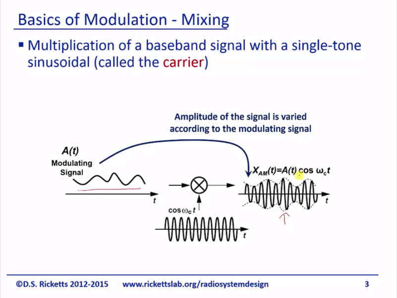
Alright, so this is a slide we had earlier in our series, which basically talked about the function of multiplication in RF systems. We have some baseband signal that we want to convert to a modulated carrier at RF and we use a mixer to mix or multiply our oscillator by our baseband signal and we typically called this our LO or local oscillator.
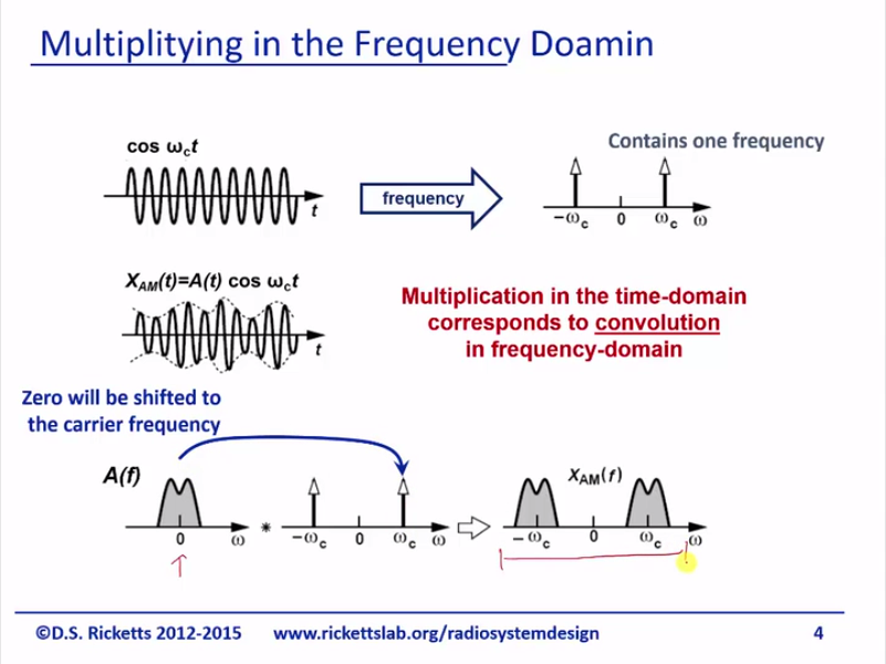
From a frequency-domain standpoint, you remember if we had a baseband signal, this multiplication took this and just routed right on top of the carrier so that we had here. So this is the function mixing in RF in this is just a review, but what we’re going to do was talk about how do we actually do this mixing or multiplication.
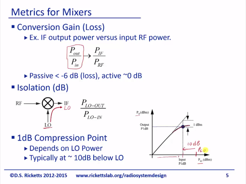
So let’s talk a little bit about some if the metrics we’re going to use to describe mixers. The first one is a conversion gain or loss; now I just tell you that most mixers have a loss, but we have a tendency to call everything to gain and then just make negative if its loss in dB. And linear loss would be to something less than 1 and typically, this is the IF output versus the input RF power. So we basically take a signal from our antenna, we down-convert it, we look at the power that comes out at IF and we compare that to the input power of the RF. So it’s Pout/Pin or PIF/PRF. You could look at it the other way where you’re taking your baseband and up-converting it and then it will be the same, you just say what’s the ratio basically my output over my input; in that case it would be RF over IF. So just this is the general conversion gain formula and you just need to figure out how you’re define it, what’s the input, and what’s the output. Typically, for passive devices, it’s -6 dB or even higher; for active circuits even without an amplifier, we can get conversion gains around 0dB and this typically is by using a switch mixer for which will talk about a little bit later. The next metric is isolation dB and the key thing here is that we’ve talked many times about not wanting LO leakage and so isolation basically is in numeric metric that tells us what is the ratio of the LO coming into the mixer and the LO component leaving the mixer and that tells us what the total isolationist is. So, it’s: and finally the one dB compression point. You remember this graph and the idea here is as my RF is increased, my “I” effort output will eventually compress and typically, this point depends upon the LO power and typically it’s about 10 dB below where your PLO would be. Typically, you have a much higher LO power than RF and as the RF power increases, you’re doing pretty well until you get to about within 10 dB of your LO and the way to think about that is your RF signal now is starting to become on the same order of your LO signal and the mixing is slightly different.
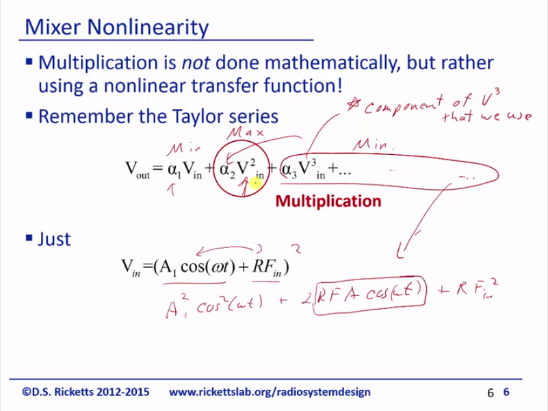
Alright, so let’s talk about mixer and nonlinearity. So, multiplication is not done mathematically, but rather using a nonlinear transfer function and this is true for any type that mixer that we’re going to use in a real circuit. We don’t have a mathematical up equivalent of mix of a multiplication and so what we do is we use a nonlinear element and if you member the Taylor series, you can see that right there in the middle of it is a nice multiplication. And all you have to do is just set your Vin equal to your baseband signal plus your RFin or in this case this would be your RFin this would be the LO and this would give you a down-converted signal. So we’re basically just using the fact that I could multiply Vin if I take squared to be a cross-term here and that’s the cross-term that will do. And what we just do that real quickly so you could see it: we have
Alright, we can see right here this is our multiplicative term that we’re looking for; so this is how we can do multiplier, but some things that we’ll notice is that if you remember from the Taylor series that a2 or our alpha 2 is usually smaller than alpha-1 and then we also have all this other junk here. So one of the challenges with mixers is to try to minimize all of these other elements and maximize the one element you want. I’ll just make a little note here there is a component of V3 that we use. So there are some harmonics of these later ones that do go to the exact frequency we want, but they’re smaller in amplitude and we ignore them, but I just want to point out it’s not strictly this and you’ll see that explicitly in a later example.
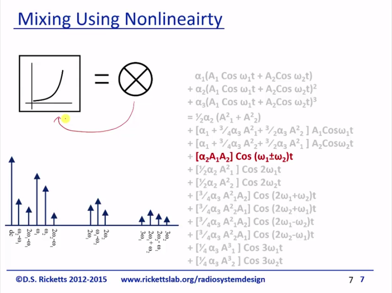
This is a plot from one of our earlier lectures where basically, I’m just showing you our mixer is a nonlinear transfer function and remember when we were doing on IP3 calculations of two input signals, this is the Taylor series and I just highlighted here for you really clear; you can see that there is a clear multiplicative component that’s exactly what we want to make a So, it’s all ties back and together we had mentioned that nonlinearity is not always bad and for mixing it’s what we actually use.
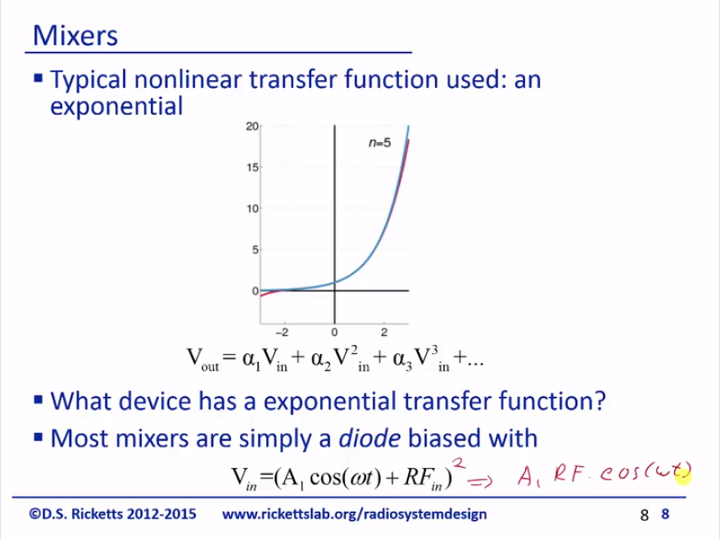
So the typical nonlinear transfer function that we use is an exponential and that’s because there’s many components that have exponential transfer functions and it’s highly nonlinear, which gives us a larger coefficients for alpha two, three, four, and five and on this is a nice animation of each end is adding another term for the Taylor series and you can see that much once we get to 8, it’s pretty well done 0, 1; so 2 is pretty significant, so is three, and then four and beyond get less than correct effect; so, that’s a nice little GIF animation from Wikipedia and what device has an expensive transfer function? I think I already had enough to this; it’s simply a diode. So we’re going to use diode’s exponential transfer function between voltage and current to create a mixing product. We’re using the input as a one because when we get squared. Don’t forget we get that component it’s as we drive to the previous slide.
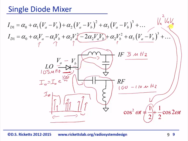
Alright so take a look at a single diode mixer. So we’ve got it here and we’ve got our single diode and I’ve labelled VA and VB and the reason I’ve done this is that the diode is the current and the diode is equal to some nominal current E to the V, EE the over VT and VBE is just going to be the difference of VA minus VB. And in lab, you can learn about these branches, but basically we’re going to have – if you look at the spectrum of ID versus frequency, you’re going to see a whole bunch of different components. So we’re going to have high-frequency components and low-frequency components and in one example that we’re going to use, we’re actually going to use a LO of 105 megahertz and an IF of 5 megahertz and RF can be the 100 or 110 megahertz, depending on which one we select. So what we’re doing here as I’m going to select this filter to allow signals from five megahertz through and I’m going to set this filter to allow signals a hundred megahertz through, but no five megahertz. And what this does is it basically separates all of the higher frequency currents are going to go through this path, and all the lower frequency currents are going to go to that path. So this is a common circuit technique to separate the high and low currents from the diode, even though in the diode, the total current flowing has many different components and we’ll see explicitly how this works in a minute. So here’s the diode current just doing a Taylor series expansion of this and I just multiplied this out and you could see that we have the exact term we’ve been looking for, which is right here as VA times VB and you can see we’ve got a lot of squares and then we’ve got feed through from both of our signals coming in and that we’ve got a cube down here at the bottom. And all I’m mentioning is these such as you can see that we have all our other components here in the diode. And this is a trig identity that becomes useful and the reason is this block will end up containing and if we multiplied it out and that actually has a DC component 1/2 that gets multiplied by this and so we get a and that’s exactly it the same frequencies as this component. So just reiterating once again, high-order harmonics do create a component at our desired frequencies, however these coefficients like alpha 3 are pretty so they tend to pass the cube and tend not to be important.
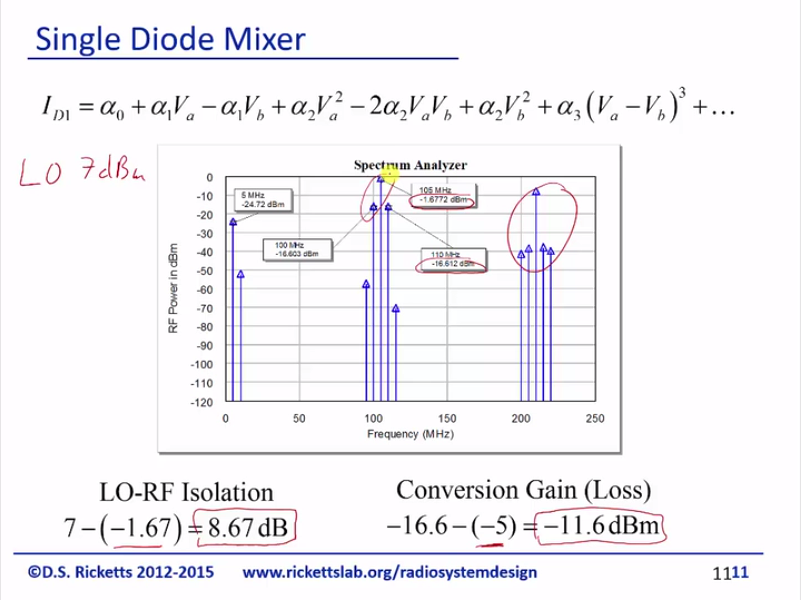
Alright, so here is the RF power out of that circuit. And once again, here’s the breakup and let’s just take a look. We can see just remember the LO is a 105 megahertz and the IF was 5 megahertz. So we can see right away the LO; we’ve got the LO here that is coming through. We’ve also got the IF coming through; we’ve got our multiplication, which should give us a 105 plus or minus five megahertz right here and that’s right here. And then we have our LO squared, which if we do , that gives us and so we have at 210 gigahertz another significant component. And then we’ve got all these little sidebands that are coming through here. So, we can see that from our equation, we can actually see pretty well the signals that are coming through and we do indeed have exactly the signals that we wanted for our mixing product; you can choose either the upper or lower sideband here. Now, the LO is at seven dBm and the IF is at -5. So let’s take a look at conversion loss in isolation; so let’s look at isolation. So the LO is 7 dBm, but we can see here that when it comes to the outputs, it’s -1.6. So, I’m looking for the difference and I see that there’s an 8.67dB isolation between the LO and the RF. Now, I’m just taking the difference because the isolation is a ratio and so I can just add or subtract the numbers in dB and conversion gain should be what our RF output is and our RF outputs, just checking upper sideband, is -16, but remember the input is -5. And so I take the difference and that means the conversion gain is -11.6dB or we lose an order of magnitude of the input signal when we up-convert it. So that sounds like a lot, but with an amplifier, we could gain that back, but in you know the RF world, 10dB is not at great thing to lose, but we deal in 10, 20, 30, 40, or 50dB. So it’s not ridiculous that we couldn’t actually use this for successful mixer. We would have to filter out a lot of other components, higher frequencies, and also if we wanted to get rid of any of these when we transmitted it, we have two find some filters to try to get rid of those.
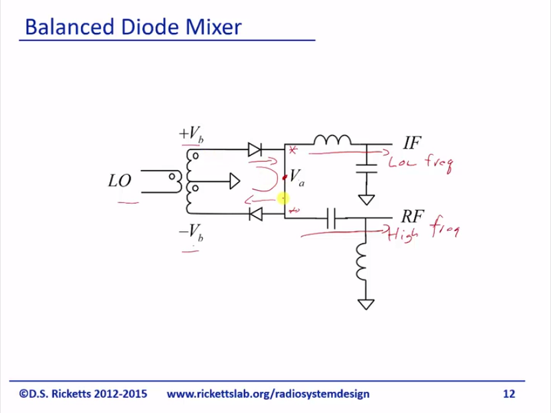
This is why people use a balance diode mixer and these two pass do the same thing; this is going to take the high frequency and it’s going to move out here below frequency. So this is low, this is the high and it’s doing exactly what we did before. It’s called a diplexer and it’s just splitting out the frequencies from the diode currents. Now, we’ve got two diodes here and you’ll notice that they have same junction here and what that means is that we end up with summing node here. So this diode is pumping current in and this diode is pumping current out, it’s just going to flow through this node and nothing is going to go into either branch. So you can already see that maybe, we’re starting to cancel some products and what we do is we take our LO and we create a plus and minus VB so that we’re going to have a VA minus VB and a VB minus VA as two of our products and we’ll do that explicitly.
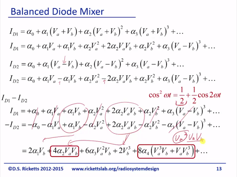
Alright, we’re going to do the math, but in the end you’ll see exactly how this works. This is just the diode equation for one diode and here expanded it. You’ve already seen this expansion before; here’s the one for the other and you notice that we have a polarity changed and that’s because we created that differential voltage and we can expand that out and you are ready can start to see that I’ve got some minus signs here where I didn’t before and what we do now as we take the difference of the two currents. Remember, it’s that summing junction that’s just going to in an easy single node; take the summation for us and so we take ID1, subtracted ID2 and if you notice, you can already see that it cancels, cancels, cancels, cancels, cancels, and we’re left with this term and this term. And if you went through and expanded things, you’d and up with – this is your final aspect and so you can see here’s the VB here’s the 4VAVB and if you’re that identity issue before noticing this DC component, it turns up this contains and this also will contain and remember this as a DC component so it will keep this frequency band. So you can see that by using two diodes, we’re able to cancel a lot of things namely we’re able to cancel the LO.
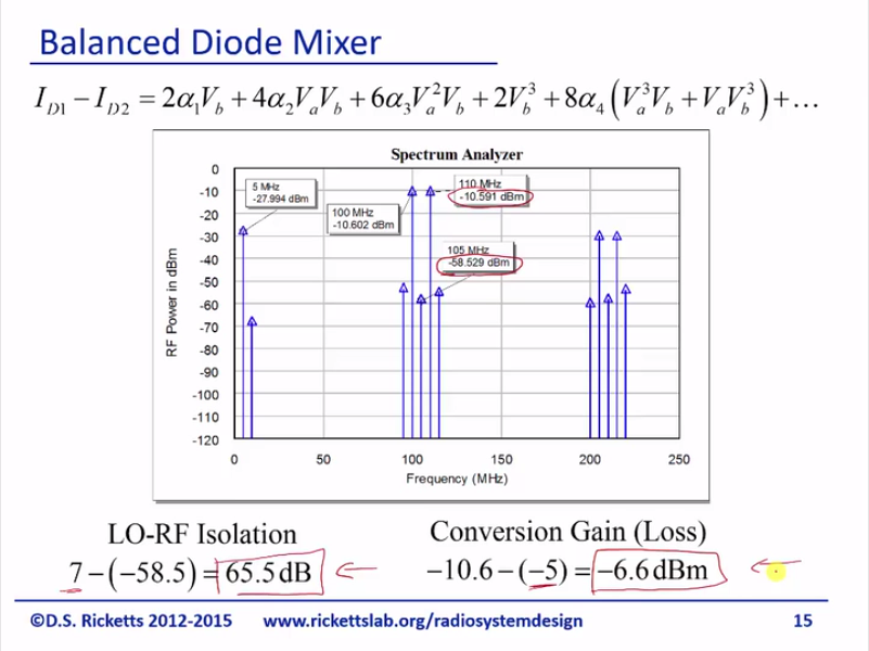
So, let’s take a look at what we’ve got here and we can see – you know we’ve got a multiplication, which is our 2 signals we want. We have a little bit of our IF coming through, but you notice that LO is really small and so this cancellation is actually been super good for us. So once again, the LO is a 105 and the IF is five megahertz 7 dBm -5dBm. Let’s calculate the isolation; so the LO is 7 and here it is -58. So we have a whopping 65dB of isolation. So right away, you can see where people use a balanced mixer when they can. The conversion gain and loss and remember the IF signal is -5, the output here look at this; it’s 6 dB higher and its -10.6 and we end up with a conversion loss -6.6dB. So, this is roughly a factor of four and so this is great; we’ve significantly increased our isolation and we’ve gotten about three-and-a-half dB higher, roughly twice or three times the output of power. So, this is a great design; this is actually used very often; it’s simple and it’s cheap and as you can see, it works great.
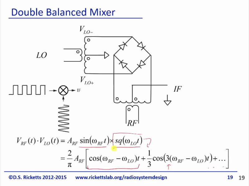
But, there’s one more topology that works even better and this is a double balanced mixer. And it looks a little bit complicated; we’ve got our LO coming in here, we’ve got our RF coming in here, and here’s our IF output. And just to help you remember I put a plus and minus here, I get a plus and minus here and a plus minus here and that’ll be important in a second. Alright, so the operation of this is to think about the LO is being very large and so when this is positive and this is negative, these two are reverse bias. So we can consider them off; these two are forward biases, but they’re the same diodes. So this point is basically a virtual ground; if it needs to source any current, it’ll come out of this node. If it needs to sink any current, it’ll go out of that node and this really is for RF is just a ground. This here’s an open and so what that means is when I have a positive RF signal coming in and I’m going to get a positive signal here and I get a positive signal here. So now let’s look at the off-set phase the LO, where we just reverse the polarities over here. Now, these two diodes are on and this is ground; now, let’s look at what happens when I have a positive RF voltage, I’m going to get a negative IF footage. So, what the LO is going to do it is going to take the RF signal and it’s going to multiply it by a string of 1, 0, 1, 0, 1, 0, 1, 0, and we know this is just a trustee square wave. So we’re going to take the RF and let’s multiply the LO and what we’re using these diodes are as our switches and it seems a little odd but if you think about it in this configuration, you’ll be no difference if I connected the node to the ground. And by using a high and low LO, we’re able to turn the two different diodes on and reverse polarity using this transformer. Our BALUN in a transmission line circuits; we talked about the rat-race coupler as a way to create a 180 degrees phase shift and this would give you these two sides; you need to have a center tap if you wanted to get a center out. So this is like a BALUN with the center tap as a transformer function. So we can think about the double balanced mixer as simply multiplying a square wave with the LO times the sine wave at the RF and so it’s a sine wave times square wave and what we can do is simply do the Fourier series of this. And if you multiply it out, you end up with and then we’re going to have odd harmonics that match up with the square wave for your series.
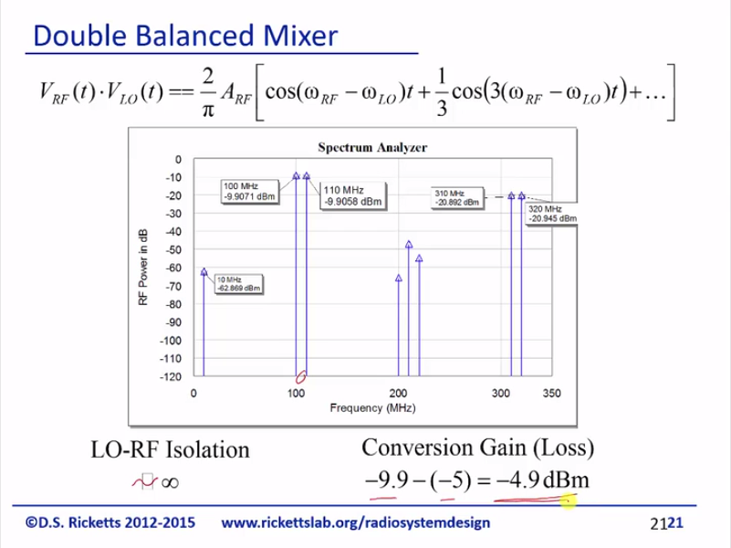
And if you look at the spectrum, you see right away that things are looking really nice. So first off, the five megahertz signal is gone and LO is gone. When I say gone, it’s really gone. So we’re just left with the two side bands and there are already higher in power. The only thing you do have to watch out is these third order harmonics are not as small; they’re only -20dB so you just have to make sure you filter these out and you aren’t transmitting these, but the second orders are small and this 10 megahertz – I actually believe comes from anyone in the upper sidebands.
And so, same as before; 7dB minus 5dB; Let’s calculate our isolation; there’s LO, so it’s roughly 0 conversion gain and loss is minus 9.9 minus 5; we end up at minus 4.9 and this is about the best you’re going to get for a mixer. There are higher order, if you will, diode configurations where you can use two double balanced mixer and try to cancel more harmonics, but generally for diode passive mixer, you’re certainly not going to get better than 3 dB loss and typically just a rule of thumb, as to say if I use a decent balanced or double balanced, I’m going to end up with 60dB of loss in particularly real circuit. This is somewhat ideal that we have here.
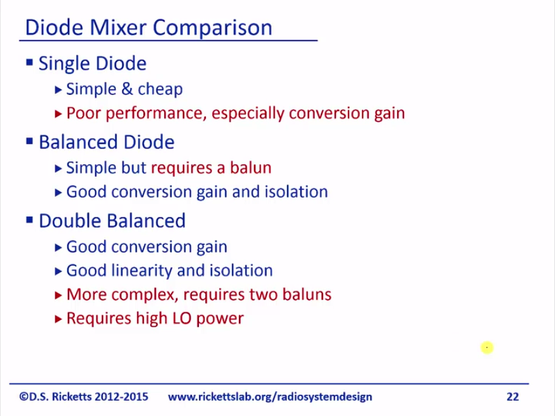
Just to do a quick comparison of the diodes; so for single diode, it’s simple it’s cheap, but it has poor performance, especially in conversion gain. The balanced diode is simple, but requires a BALUN, requires a single to differential conversion which is not trivial unless you have some transmission lines to do it or at lower frequencies; you can do it with a transformer, as good conversion gain and isolation. The double balanced mixer has great conversion gain, good linearity, and isolation. It’s more complex and you need two BALUNs. So typically if you’re going to build a radio and the mixers that we’re going to use in our final projects, we’re all going to be double balanced mixers sold by many circuits and they’re about 50 bucks a piece. If you’re actually build your own for radio circuit that will probably cost you somewhere around 10-40 cents depending on height the balance whereas a single diode mixer is cheap as it’s just cost a few pennies. And the other thing is a double balanced mixer does require high LO power because we want to try to turn those diodes on and off…