
Low Pass Filter
In this part of the workshop you will design a low pass filter that will filter out radio signals above 1 Ghz. We build a low-pass filter as the band-pass filter designs, which would better isolate our targeted 950 MHz carreier, are very inneficient with the fabrication/construction we use for our quick-build process.
To design a filter, open the workshop template.
Go to the tab on the left, called Project, open and look for the item iFilter Filter Synthesis Tool. You can see this option on the lower left of the image and also the filter GUI that will open up.
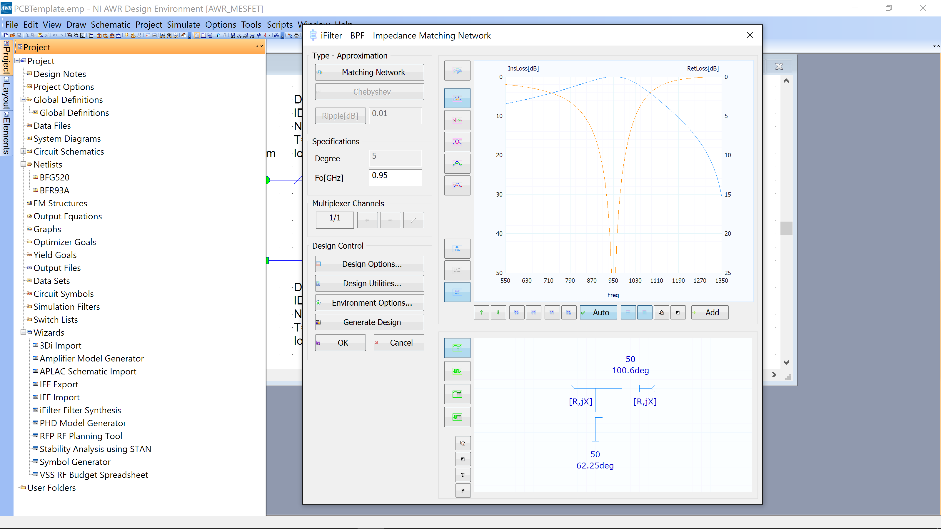
Click on the top left button. In the image above it has the word “Matching Network” – yours may have different words. In the filter GUI that opens, select Low Pass Filter, Microstrip, Distributed Stubs Filter->Double Radial Stubs.
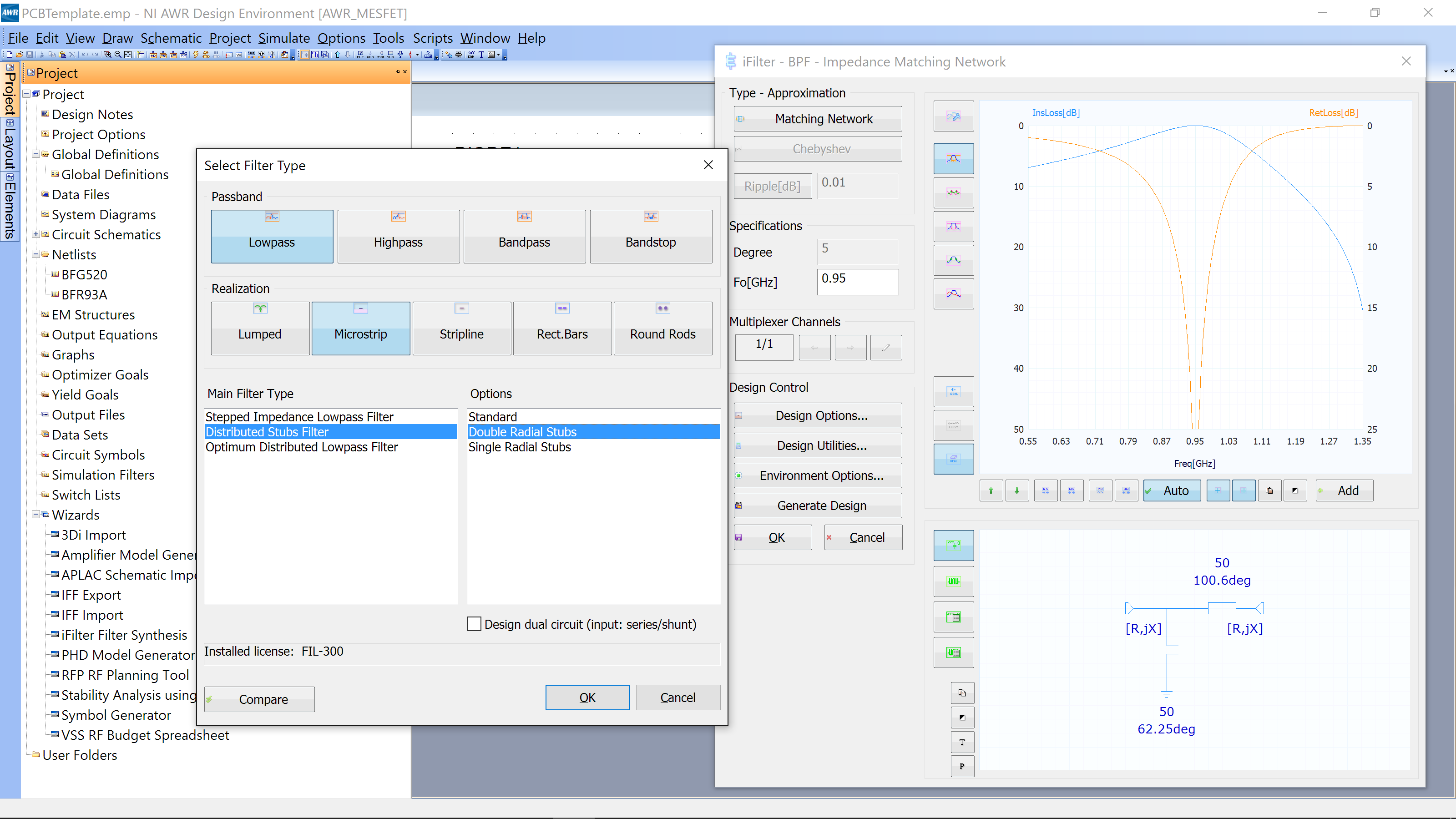
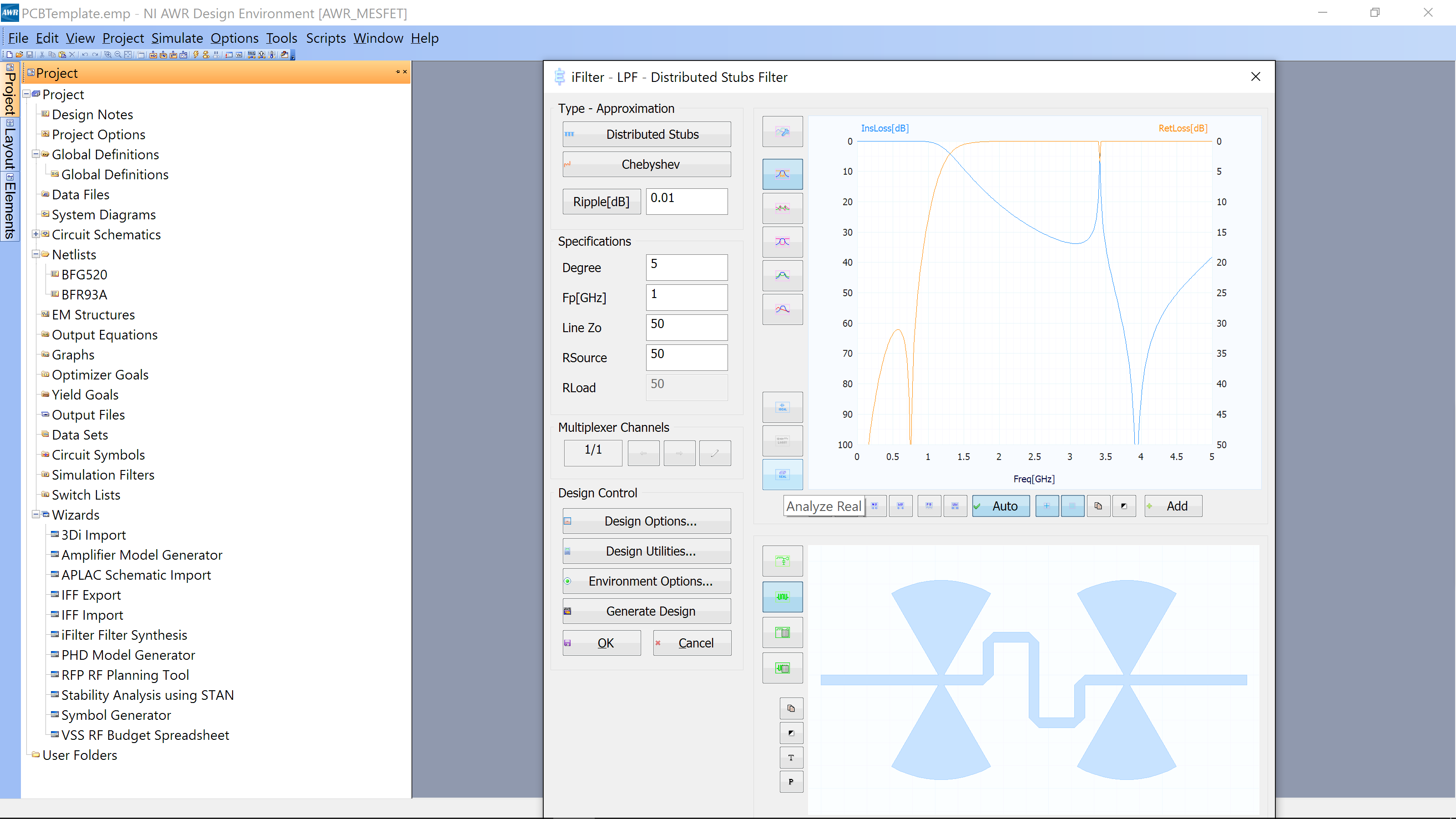
The following GUI will open.
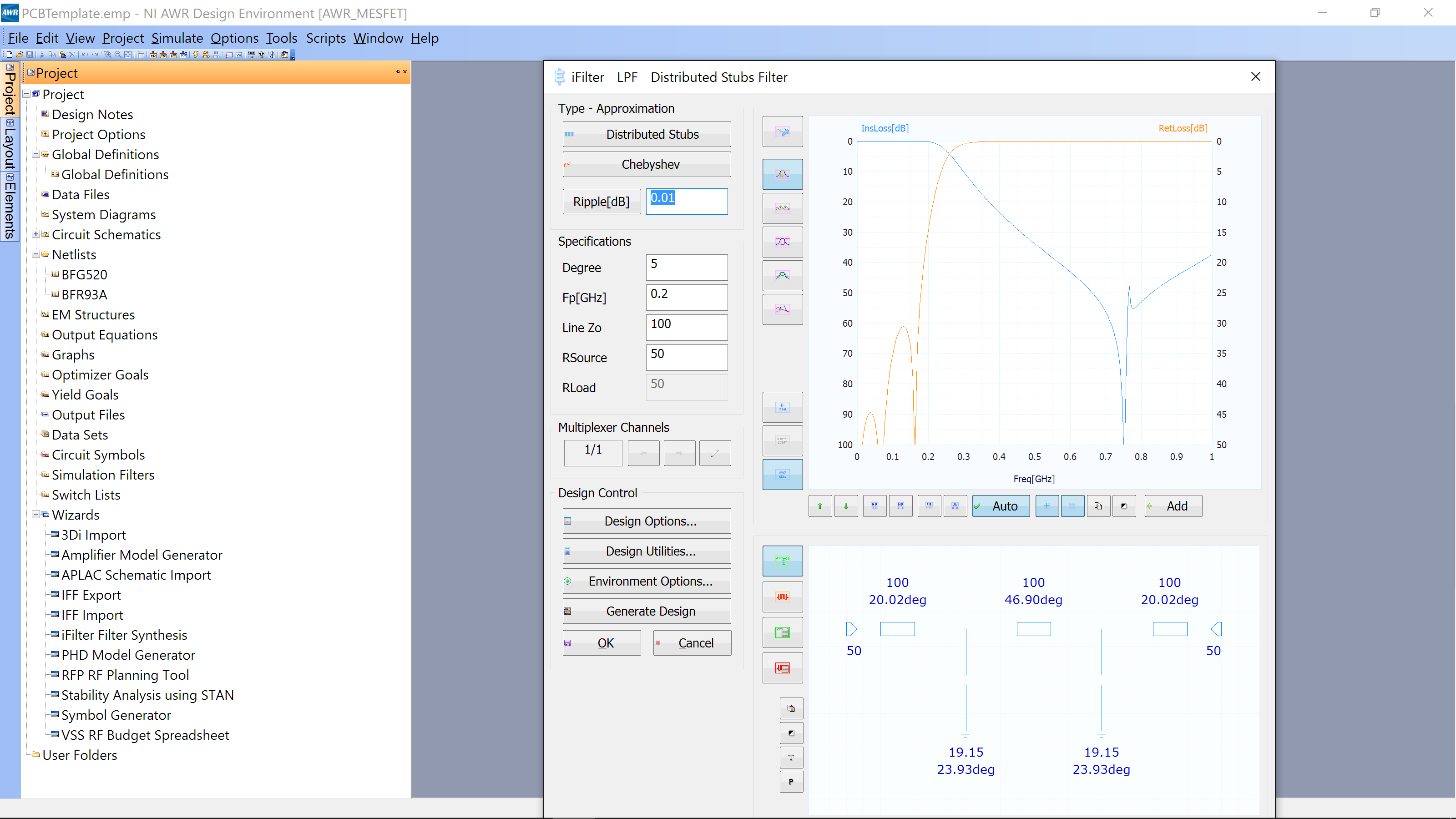
Change the Fp to 1 GHz and the Line Zo=50 Ohms. Then click the button for View Layout, the button can be seen by the mouse cursor below
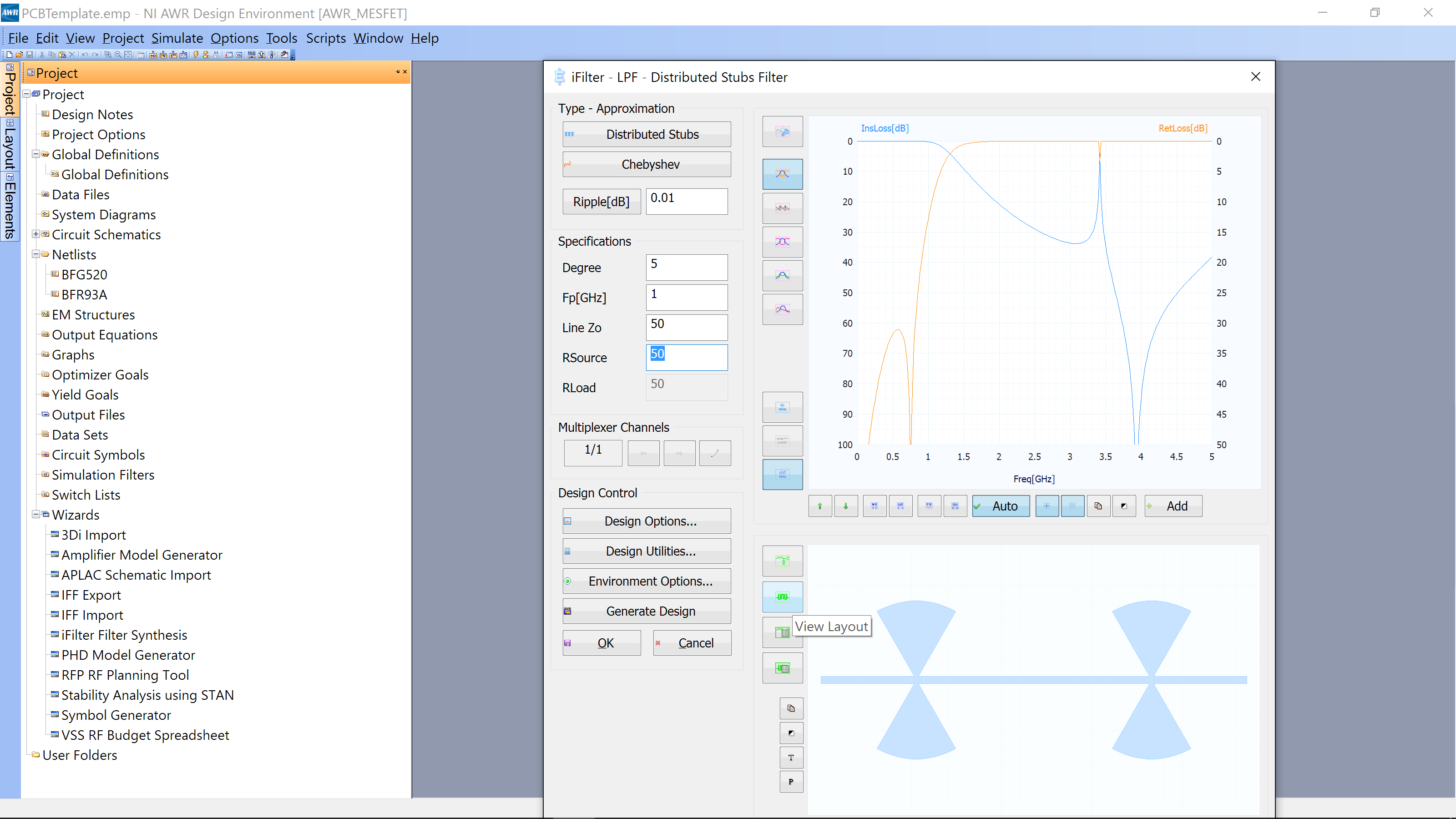
You can now see the layout of the filter. You can make the filter more compact by selecting Design Options then Bend/fold long lines when appropriate.

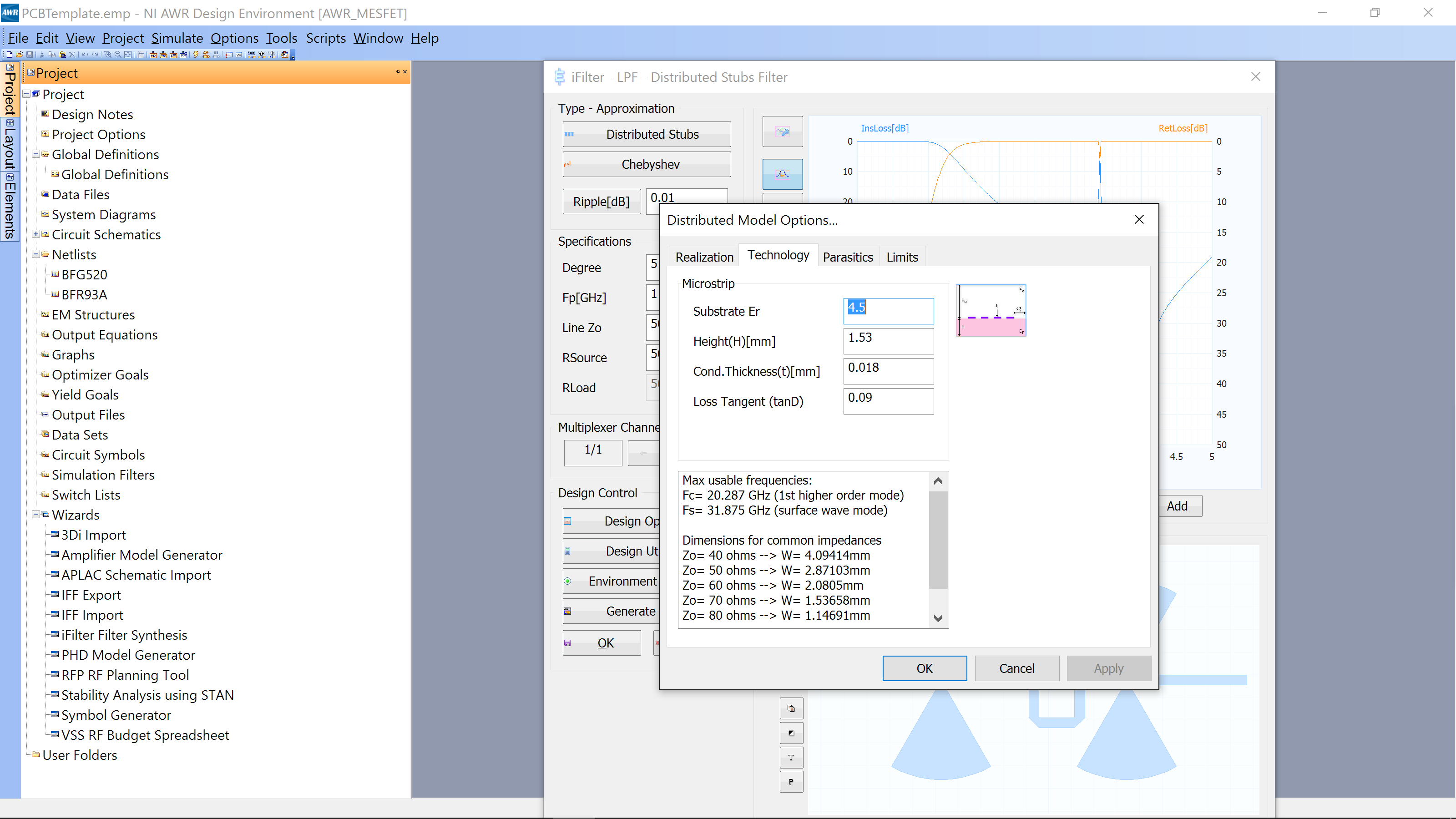
Also in the Design Options menu is the Technology stackup. You can check to ensure it is correct. Below is the correct stackup.
Now Click the icon for Analyze Real (see the cursor and pop up label below)
This will ensure that the design is made with a layout for simulation and fabrication.
Now click the button Generate Design and the following will appear
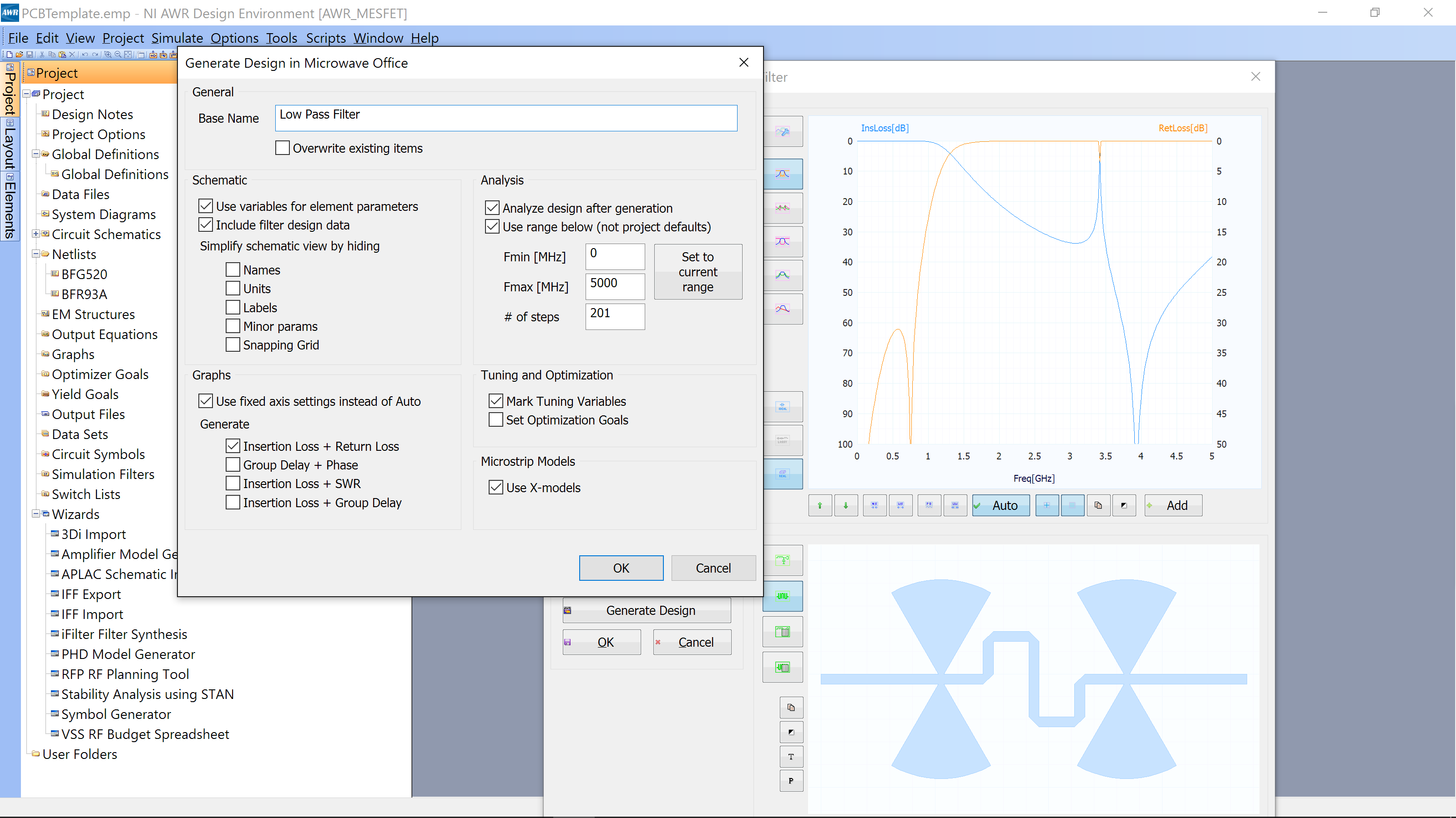
We changed the name to “Low Pass Filter”. You can review the options that are checked. Basically, it will setup a simulation and run it when you click OK.
After the simulation, you will need to close your filter design to see the S-param simulation. You can view both the schematic the iFilter created as well as the simulation results by going to Window->Tile Vertically:
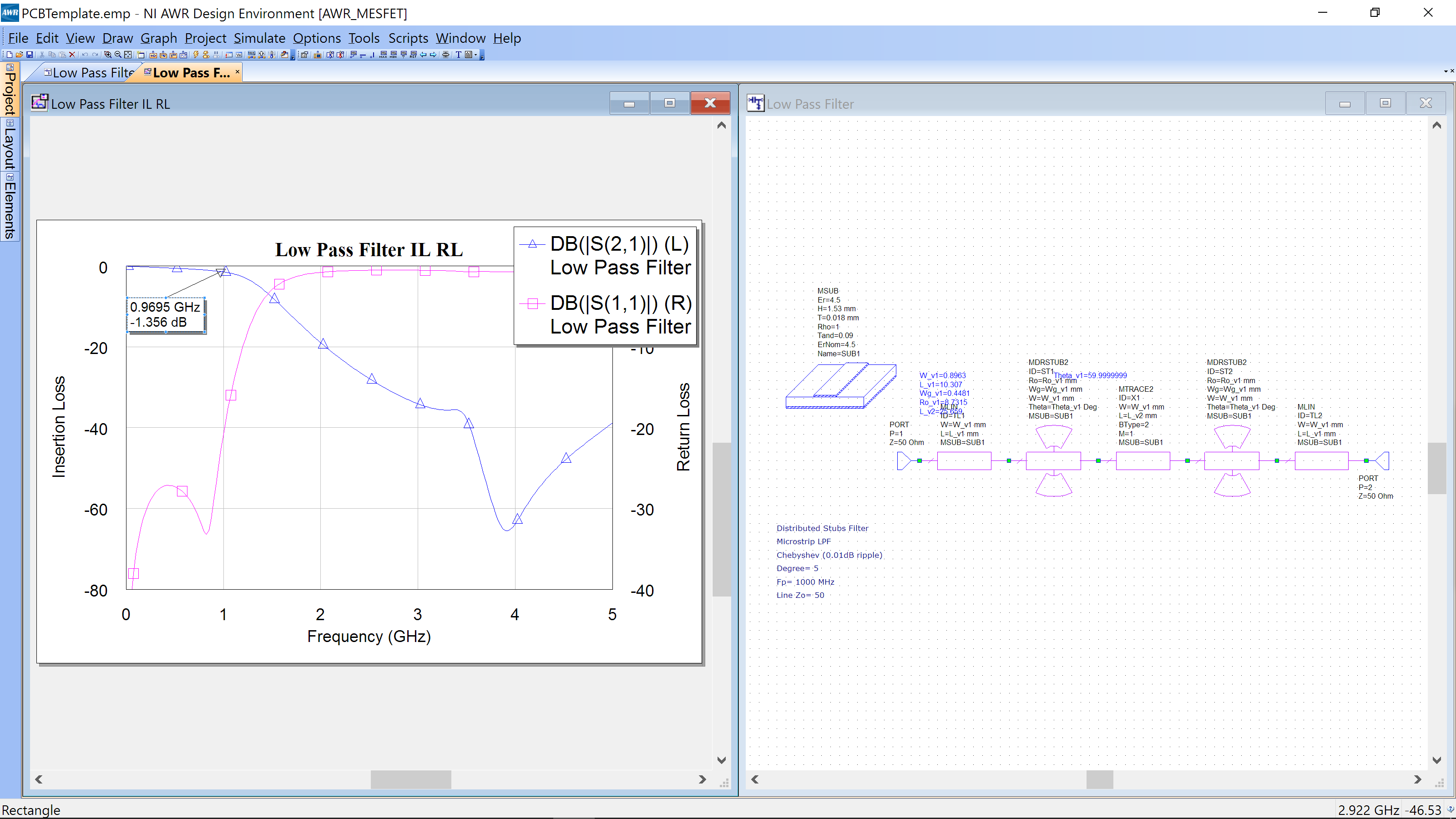
The design has a pass band below 1 GHz, with the loss at 950 MHz of approximately 1.35 dB. You can also see the schematic of the design that was created.
To see the layout, click on the schematic, then go to View->View Layout.
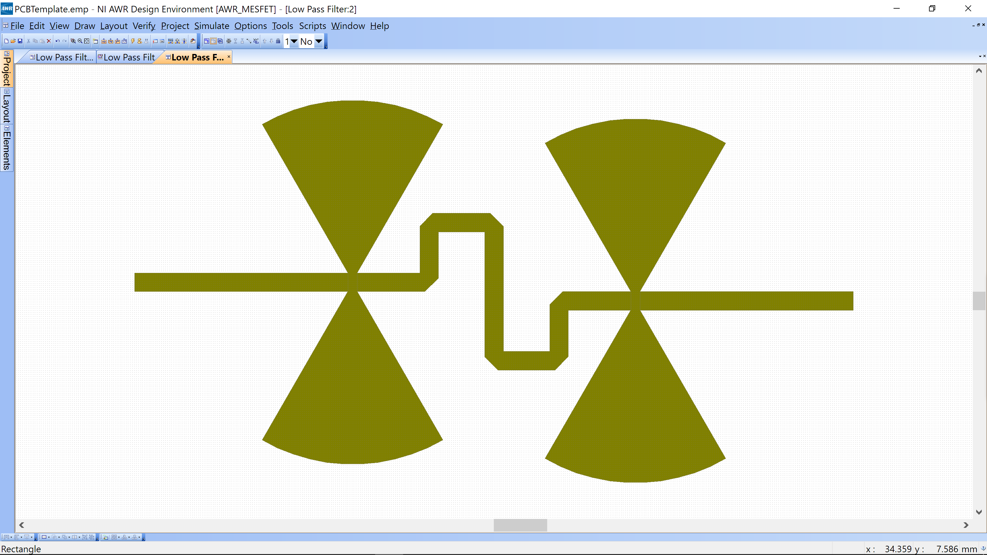
You are done with your design. You just need to go to Layout->Export Layout and then save as a hierarchical .dxf layout.
Proceed to the fabrication pages. You can solder SMA connector directly onto the left/right transmission lines since we set hem to 50 Ohms.

Testing
To test your filter, simply calibrate the VNA and measure S21 and S11 of your filter.