
This lab is different from previous labs in that it is not a step-by-step experiment, but rather a design project.
GOAL: You will have to design and verify a super-heterodyne receiver. The input signal consists of a desired transmitted tone at 592MHz as well as undesired interference.
Challenge: Choose LO and IF frequencies to meet the specifications which are provided.
As in any engineering task, there will be trade-offs and you should clearly motivate your choice of frequencies. NOTE that there is no unique “Right” or ‘Wrong” solution to this assignment. If your answer fulfills the requirements, it is obviously a correct design.
Please download the NI/AWR Design Environment file called “MY_RX.”
The system diagram looks like this:
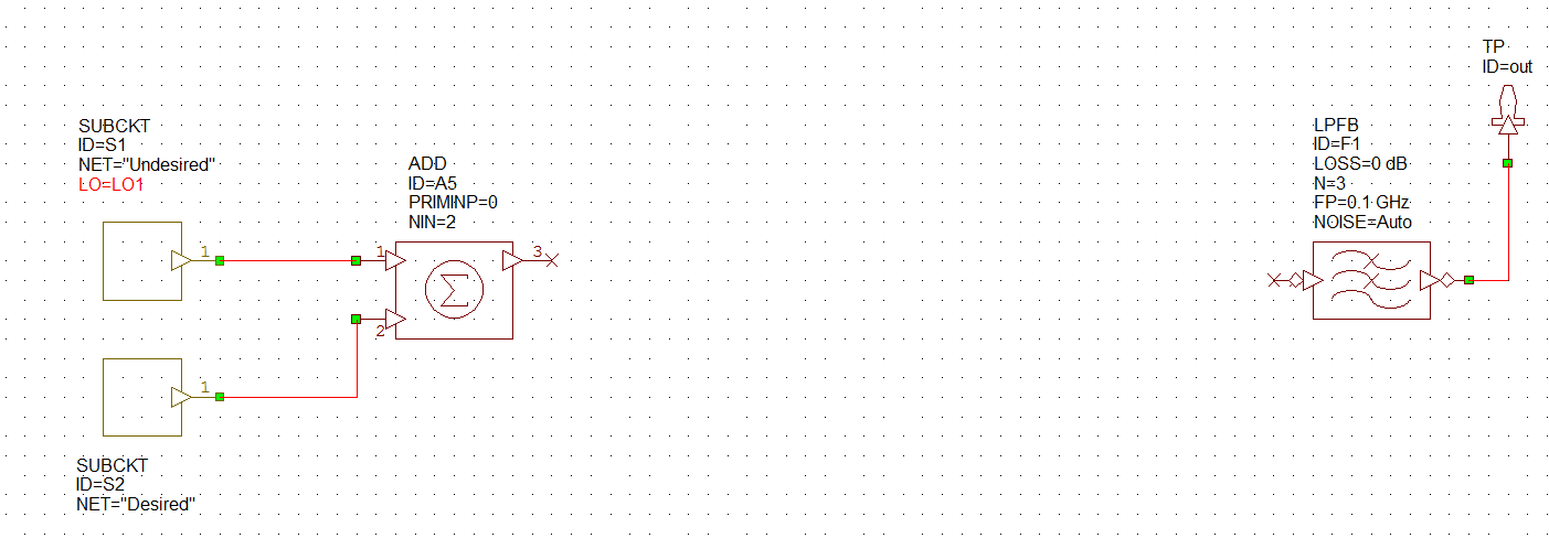
The signal you are trying to receive is located at 592MHz. There is a low-pass filter provided at the output with 100MHz bandwidth. This is the smallest bandwidth you can have for a LPF.
Spectrum of the test point “out” should meet these requirements:
- The desired input signal can be converted to any frequency within the band of the output filter and the level should be at least 0dBm.
- If there are other frequency components visible on the spectrum at the baseband, their amplitude should be at least 35dB less that the main signal.
- To test image rejection, there should be no signal higher than -40dBm when the desired signal is absent. (The image is just the non-desired signal, so if you turn off the desired signal, what remains is just your image and interferers).
- You are restricted to 20% fractional bandwidth for filters with a center frequency greater than 200MHz and 10% fractional for filters less than 200MHz.
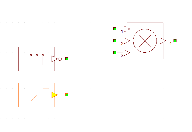
In your design you can use an “ideal” mixer to do frequency down conversion. This can be implemented with “MULT” block in NI/AWR Design Environment. The third input can be used to represent gain of the mixer.
CRITICAL: Make sure your first LO frequency is set by a variable called LO1 (LO-One) all capitals.
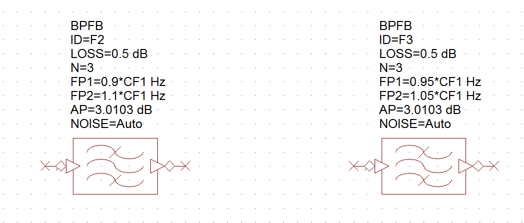
Your design will need band pass filters as well with a specific center frequency and fractional bandwidth. One way to implement a filter with fraction bandwidth is shown below. Here CF1 is a variable denoting center frequency of the filter. You are restricted to 20% fractional bandwidth if CF is greater than 200MHz and 10% fractional bandwidth if CF is less than 200MHz
At the end of this lab your submitted solution should include
- A diagram of your designed receiver
All settings of components should be visible, i.e. one can see the center frequency and bandwidth of all filters, one can clearly see the LO frequencies. - Spectrum of test point “output” once with and once without the desired signal (you can disconnect or disable the “Desired” sub-circuit from the input adder).
- One paragraph explanation about the operation of your circuit and how the IF frequencies were chosen. It is good to explain the tradeoffs you encountered.
Comments are closed.