Geting started with AWR Microwave Office
You must use a 64 bit Windows operating system (Macs running Windows are OK).
For those given a USB stick at a workshop, please follow the directions below. Alternatively, if you are a student or faculty (.edu email address) you can obtain software and a 120 day licences here. If you are not affiliated with a university (a .edu address), you can request a 7 day licence here, this license can be extended if you are participating in a SDC or Workshop by contacting the SDC/Workshop Bits2Wave instructor.
The instructions below are similar for all software installations.
|
|
- Open the Template file from the template folder on the USB: PCB_Template 9_25_2017_2D_Cutter.emp
- Select File->Save As and save as “Lastname_setup_example_v1.emp” where Lastname is your last name. Always have your name in the file name and always work on a copy of the template, not the original template file.
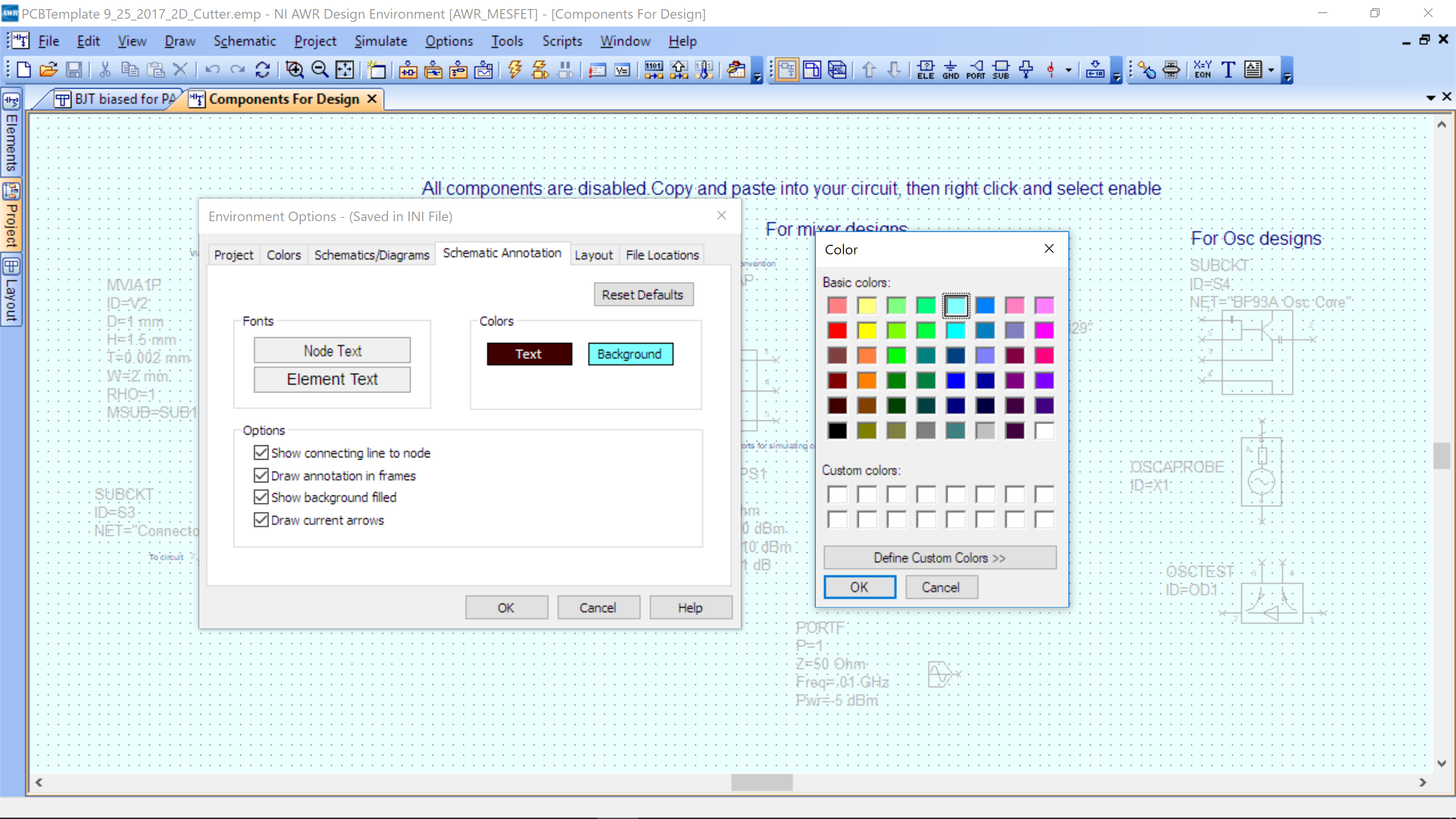
- In the Menu at the top, select Options->Environment Options and select the following schematic Background color (you will navigate to the Schematic Annotation tab to get to this screen shot)
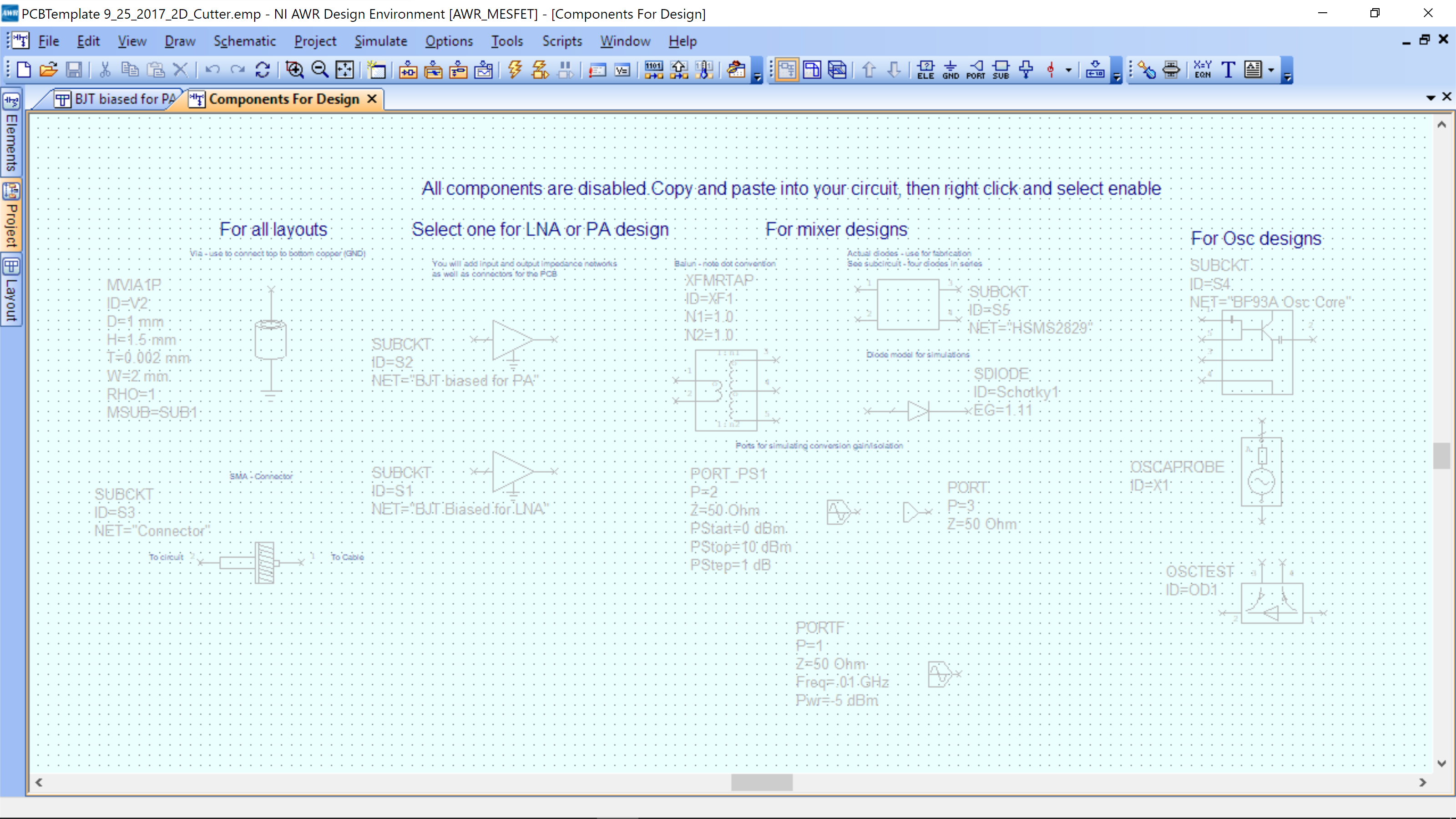
- Select OK and OK, and you should see the schematic Components for Design with disabled components (gray – disabled; black – enabled). This can also be found by using the left tab Projects->Circuit Schematics and selecting Components for Design.
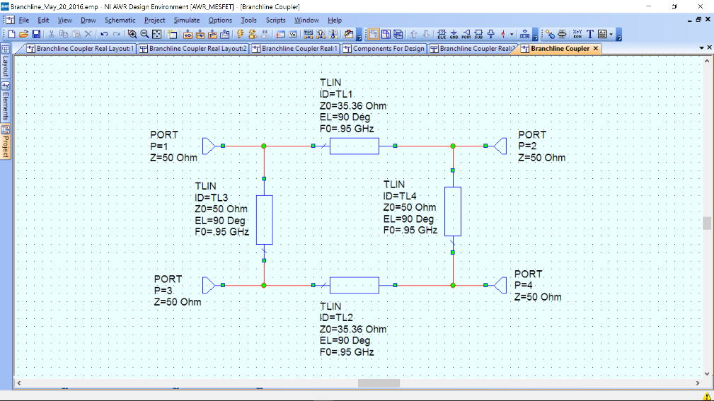
- Create a new schematic design and call it “BranchLine ideal”, Project-> Add Schematic-> Add New Schematic.
- Add four TLIN elements and four ports and connect them as shown below. PORT and GND can be added directly from the tool bar at the top of the software (labeled “PORT” and “GND”). All other elements can be added by Ctrl+L then type the name of the element, e.g. RES or CAP, and you will find it in the list that appears. You can rotate a component by Right Click-> Rotate
- To connect, simply move the mouse to a terminal and an icon of solder will appear, click and then route terminals together.
- Set the parmeters as shown in the schematic by double clikcicking the parameter and changing the value.
- Setup the simulation by going to Options->Project Options->Frequencies and setting the range from 0 to 4 GHz in 0.01Ghz steps. Hit Apply and make sure replace is selected.
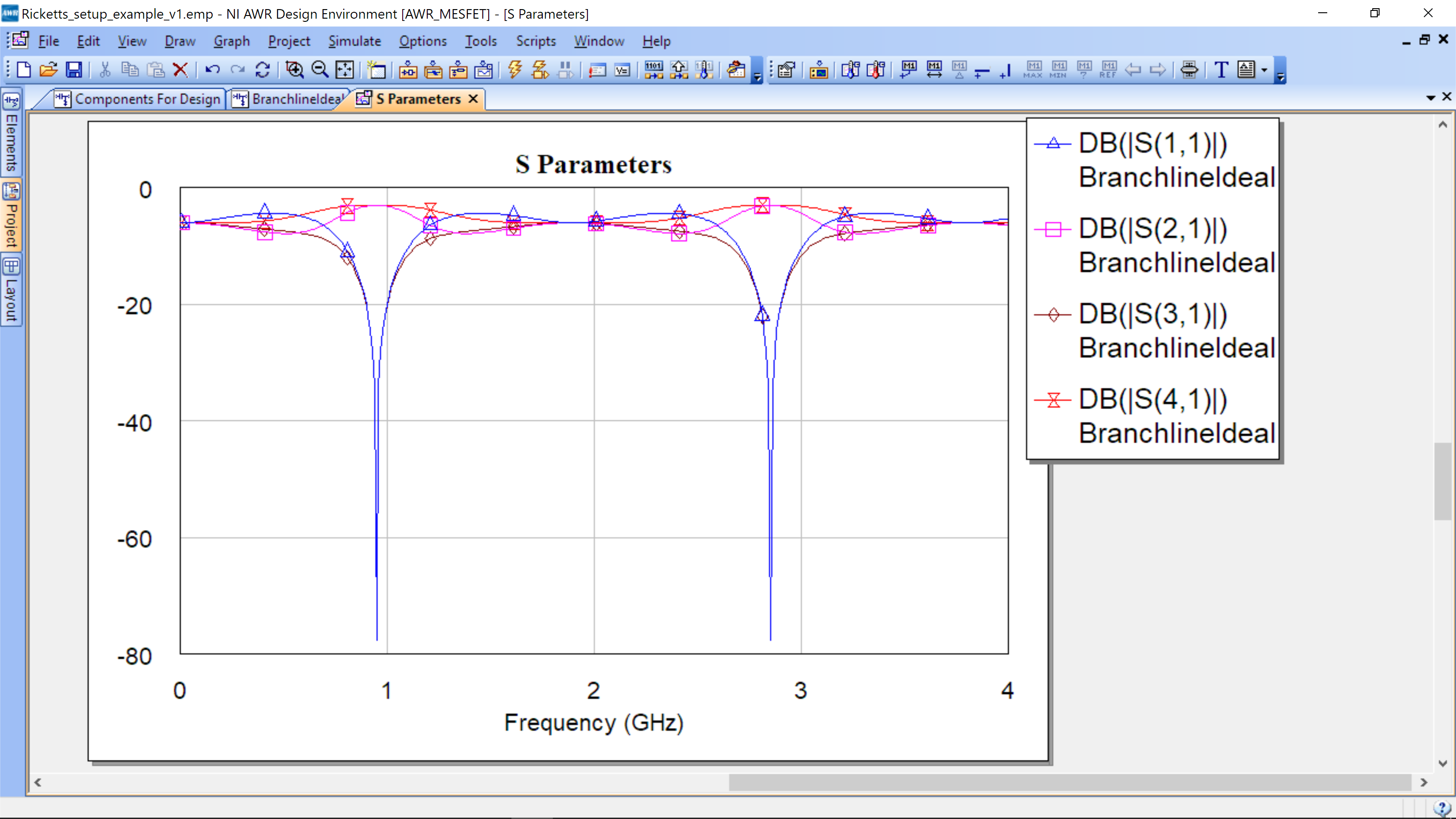
- Add a Rectangular graph, Project->Add Graph->Rectangular. Name graph “S Parameters.” After graph is created, Right-Mouse Click->Add Measurement.
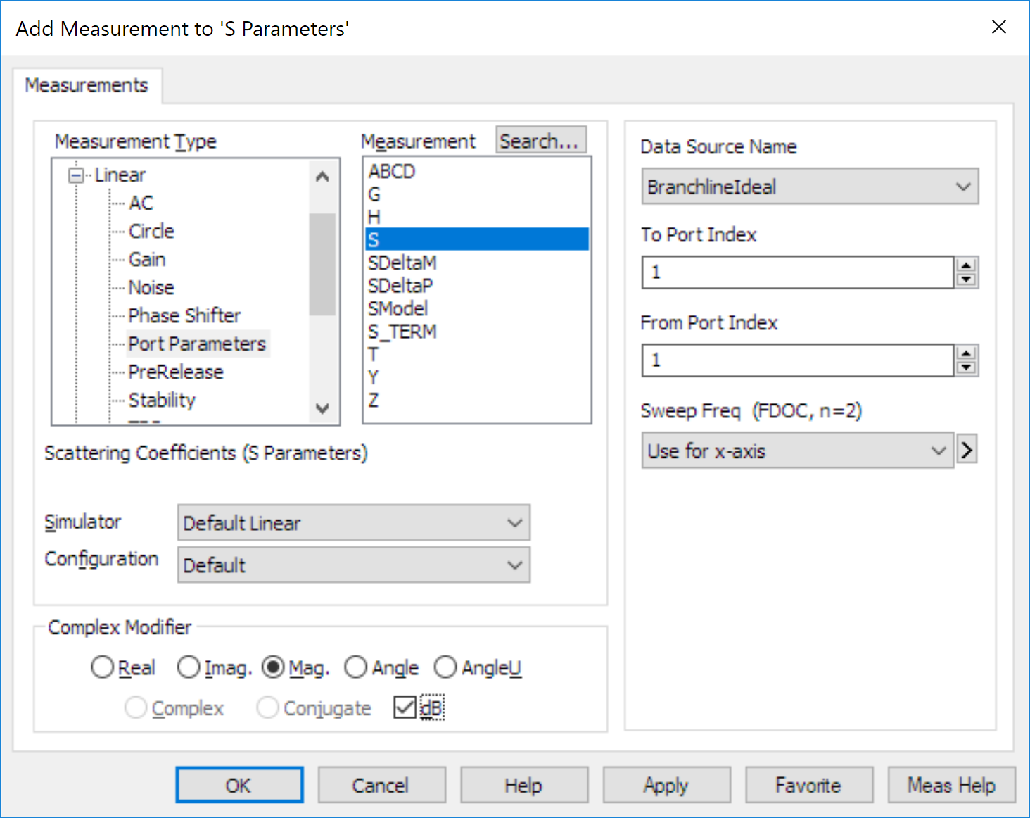
- Make sure Data Source Name is “BranchlineIdeal” and not All Sources.
- Add a measurement of magnitude of S11 (port 1 to port 1), S21 (port 1 to port 2), S31 (port 1 to port 3), and S41 (port 1 to port 4) in dB scale. You can hit Apply, then change measurement, and hit Apply again to make additional measuremeent.
- Run the simulation by selecting the lightening bolt icon located under the Tools menu (it is not in the Tools menu, but is located just under the word Tools and Scripts).
- You should see the image below with similar magnitude values.
- Click on the Components for Design window, then go to Window->Tile Vertically. Your scheen should look like this. Please have this EXACT SCREEN on your laptop at the beginning of the workshop so the staff can see you completed all steps properly and are ready to start!
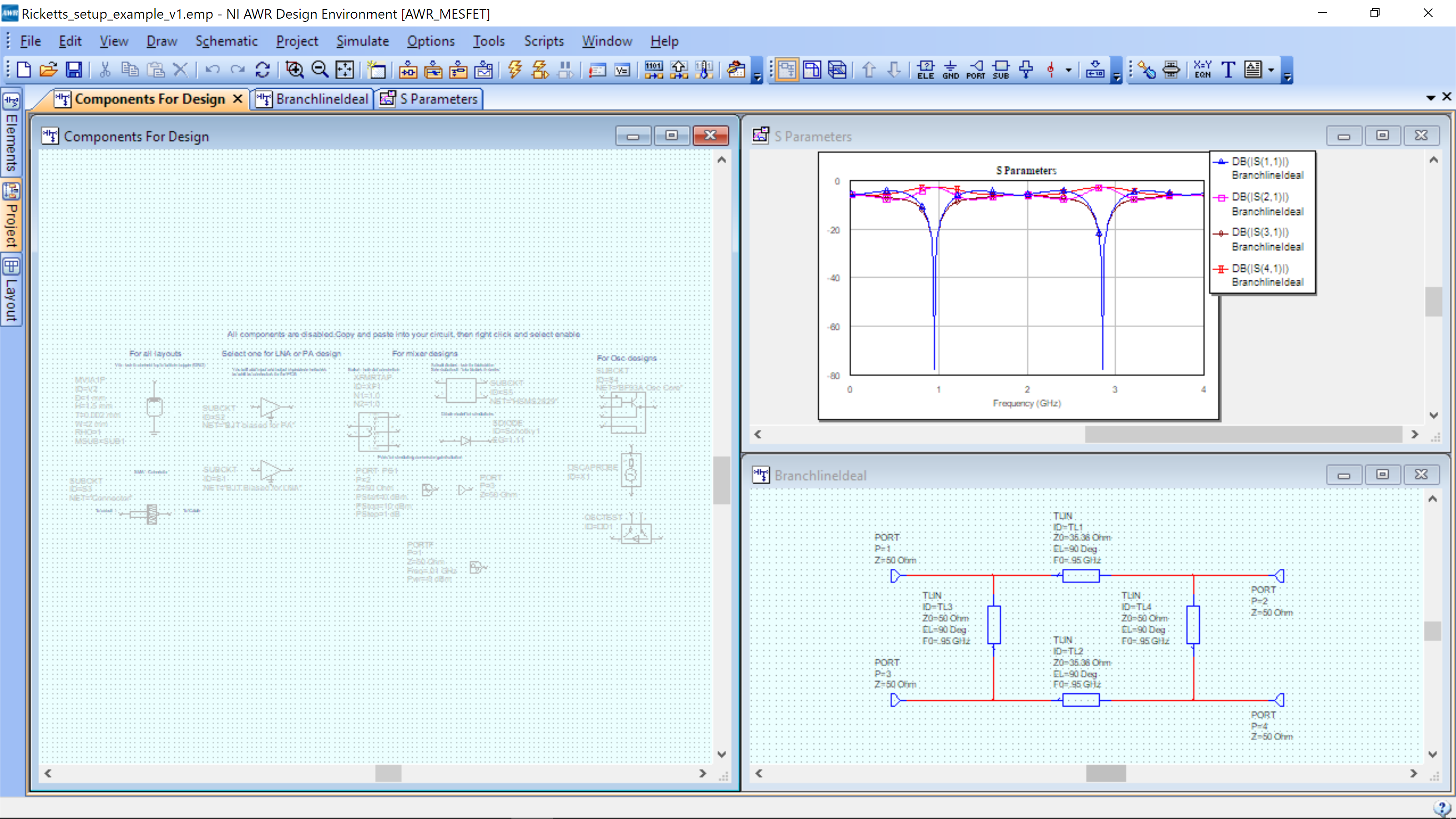
If you are at an in person workshop, Open to exactly this setup/screen at the start of workshop, so that staff can check your setup.