
Fabrication – Mask Preperation
Creating the Mask
Printout (flipped from desired copper design) is copied onto a PCB transfer paper. The print is composed of small balls of styrene, which we will melt onto our copper PCB and use as our etching mask for the PCB. A copier is used in the workshop to ensure the toner output is known. Modern laser printers reduce the darkness of toner for efficiency and aftermarket toner replacements reduce the content of styrene. A laser printer can be used if its advanced settings are adjusted to a very dark setting and a high-quality toner is used (typically one from the printer manufacturer, e.g. HP or Canon). An inkjet printer or a Brother laser printer cannot be used as its output is not styrene (plastic).
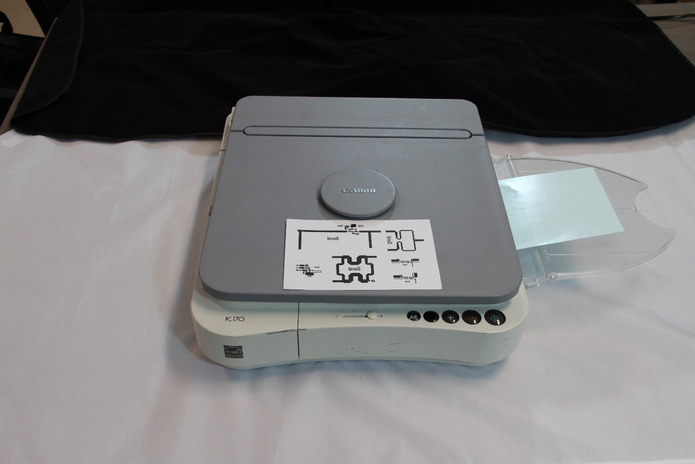
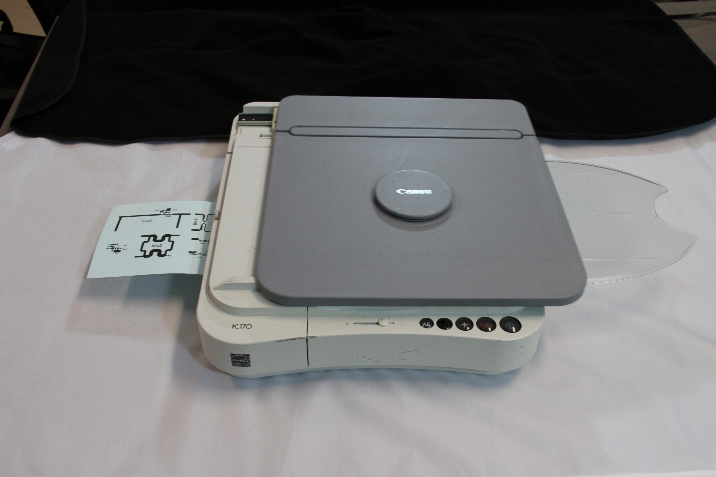
The paper (blue in color) is normal paper with a water soluble Dextrin coating (see www.pcbfx.com). This simply makes it easier to separate the printed layer from the paper. Normal photo paper (glossy) could be used, but the release of printed layer takes longer in water.
Preparing the PCB
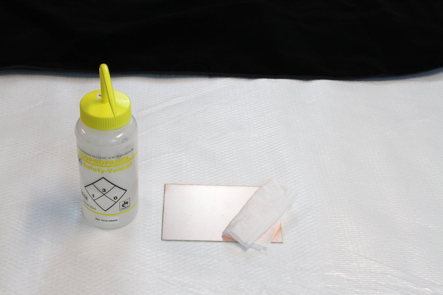
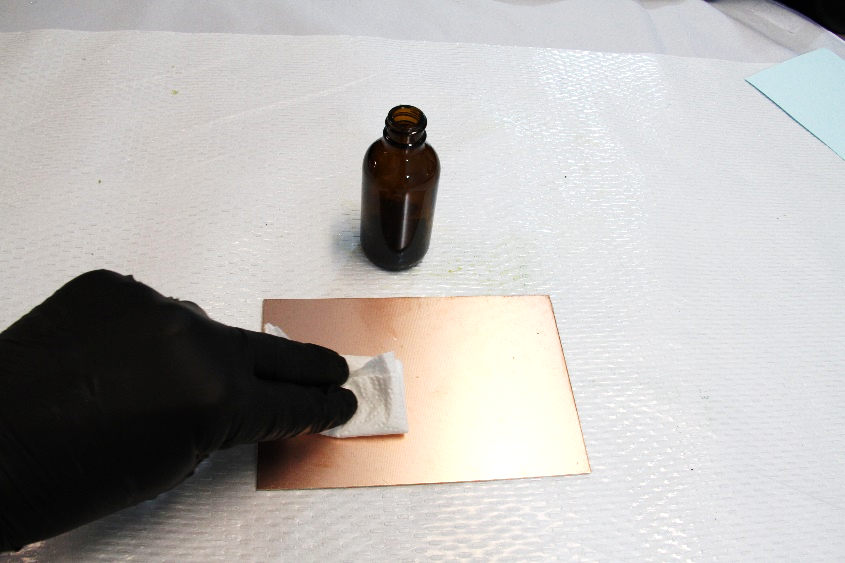
Take your PCB and clean the top surface. This is best done with dish soap and water and an abrasive sponge. The soap will remove oils and the abrasive will remove oxide. If running water is not available, you may clean with isopropyl alcohol.
Place the blue transfer paper over the board
Trim the paper so that the sides are even with the board and the front/back are slightly longer (2-5 mm). Trimming even to the sides assists in handling the board.
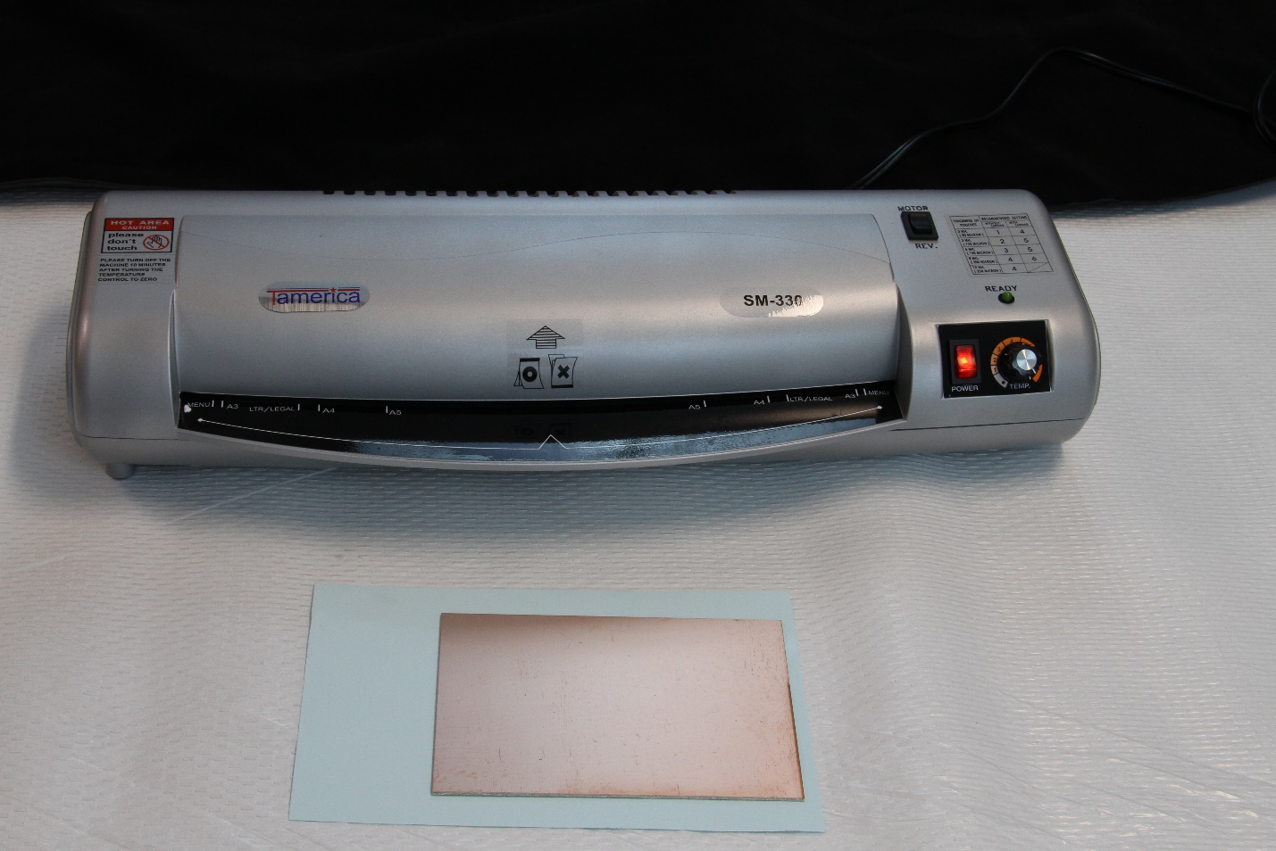
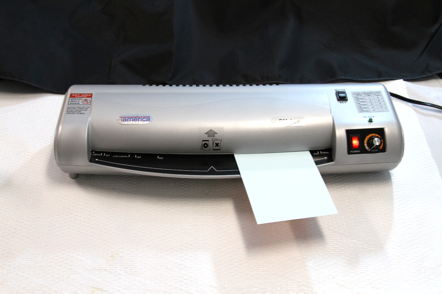
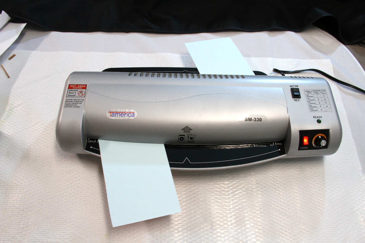
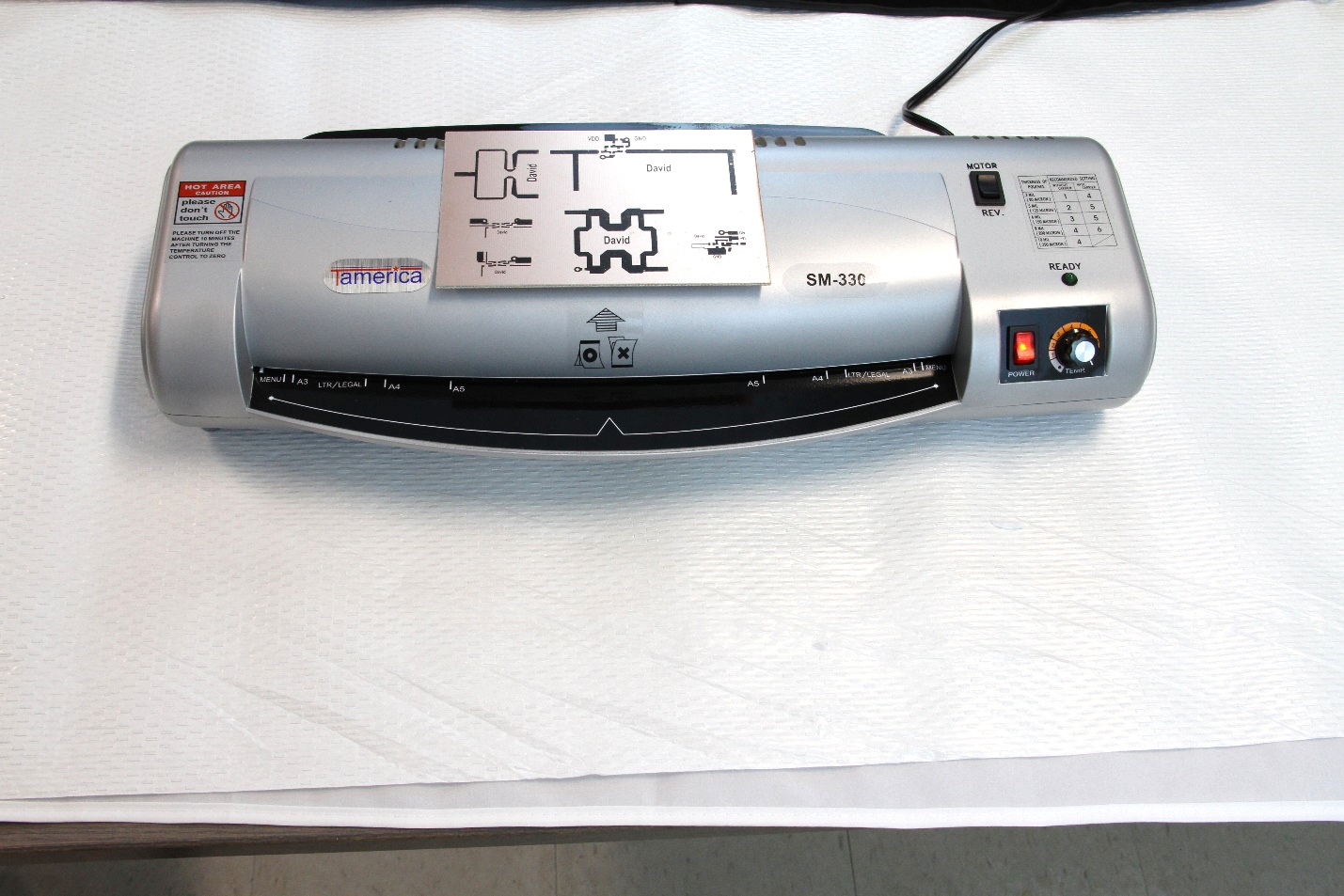
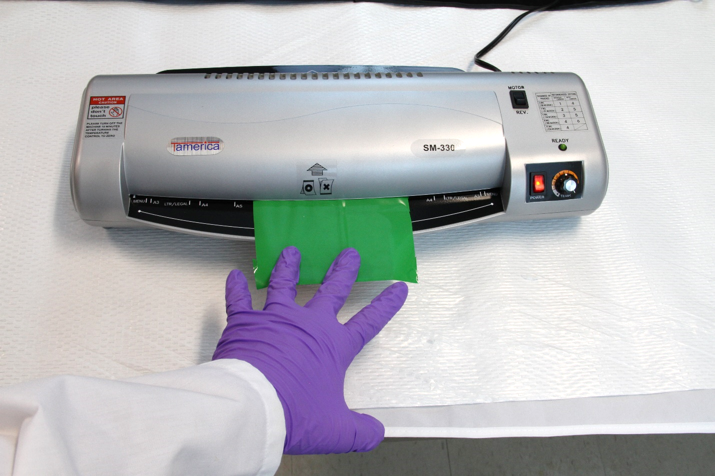
After transfer of the layout (flipped) to the transfer paper, the plastic styrene will be transferred to the copper layer on the PCB by thermal transfer. This is just adding head and pressure to melt the plastic and adhere it to the PCB. You may use a household iron, but the results are hard to replicate if you are not experience (and using your own iron). We will use a laminiator, commonly used for laminating plastic covers. The model we will use is a Tamerica SM-330. This has been shown to provide the necessary heat, speed and pressure. Other laminators may work, however you would need to test the time and number of passes to ensure adhesion.
Transferring the Mask
Place the PCB with the paper on top into the laminator at a slight angle (5-10 degrees). The angle will assist in the laminator grabbing the PCB. Ensure that the back edge of the PCB will clear the laminator side, otherwise the board will not go completely through.
Ensure the PCB
will pass through
During the workshop, you can run two boards at once. It is recommended that they be placed in one after the other, like below.
Pass the PCB 5 times through the laminator, placing the same edge into the machine each time.
Rotate the PCB so that the back edge is facing the machine, and pass the PCB through 5 more times.
Rotate the PCB so that the original edge is facing the machine, and pass the PCB through 5 more times.
5 times – rotate 180 degrees – 5 time – rotate 180 degrees 5 times.
Your PCB should have gone through 15 times. Often fewer passes are needed, but depending on the warm up time of the laminator and other ambient conditions, less than 15 can result in non-ideal results.
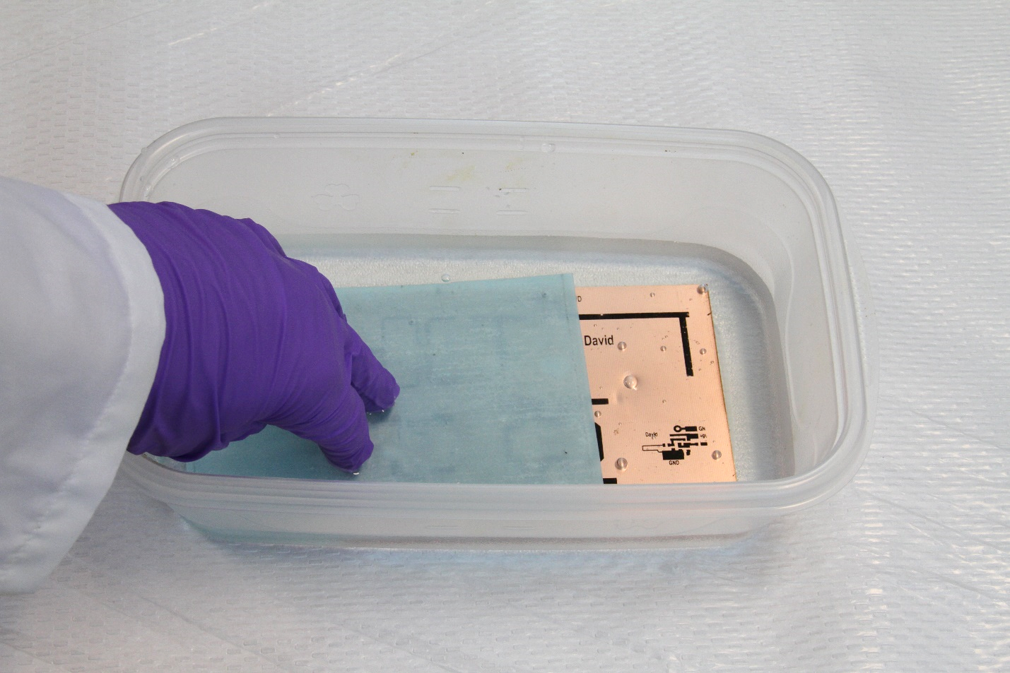
After your 15th pass, place the PCB in water.
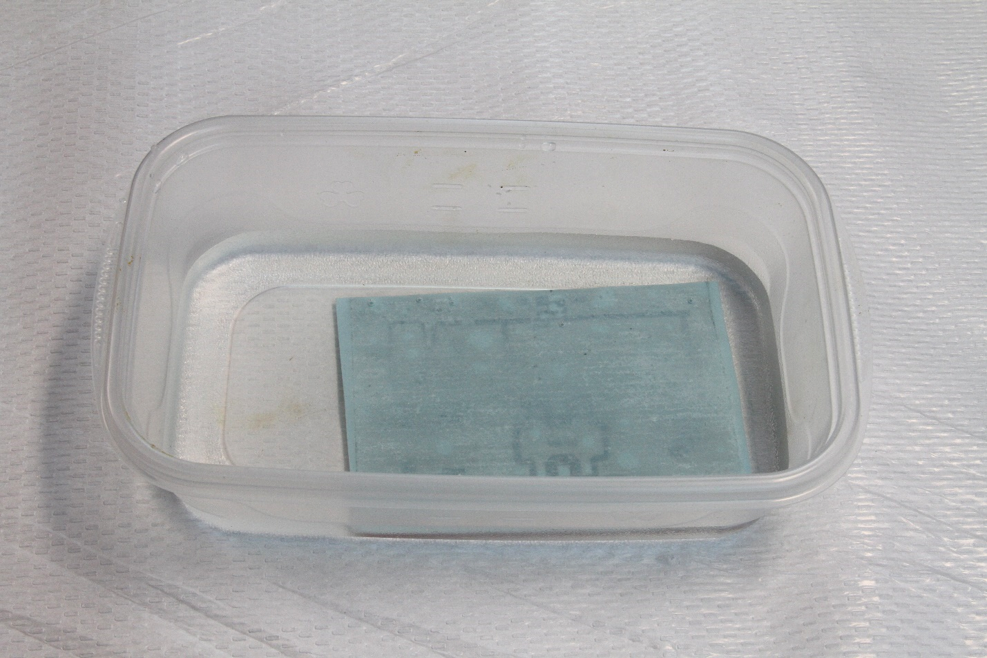
Let sit for 1 min. Then gently move your figners left and right on the paper, until it is fully separated.
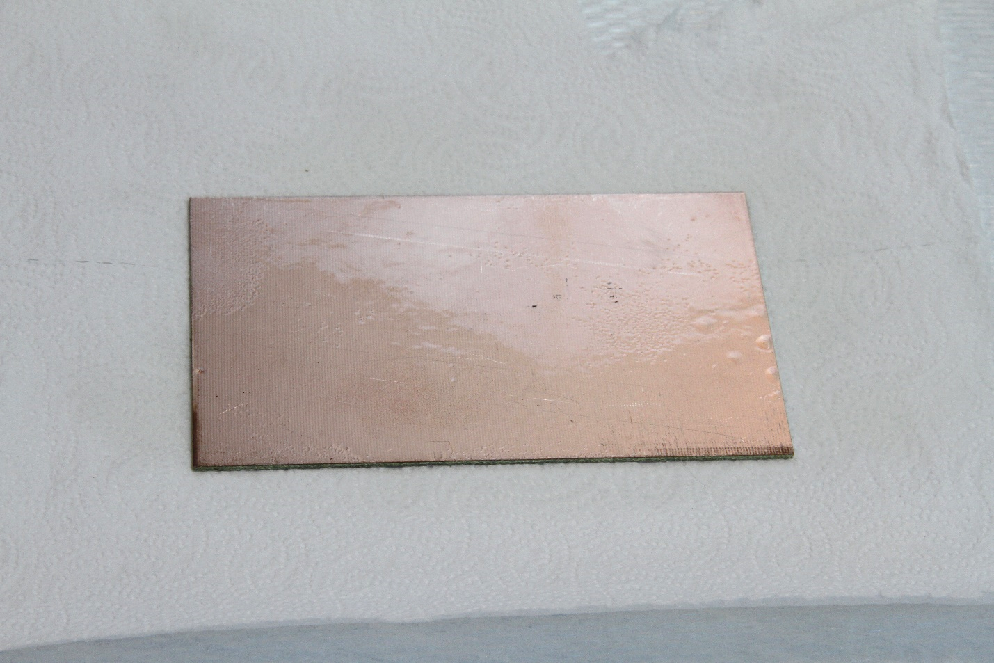
Remove the PCB and lay it on an absorbent paper towel. You can gently dry the top. If water is available, take the PCB and run the side with the transferred toner under a warm faucet. Then gently pat dry. Heavy pressure and rubbing will remove part of the toner.
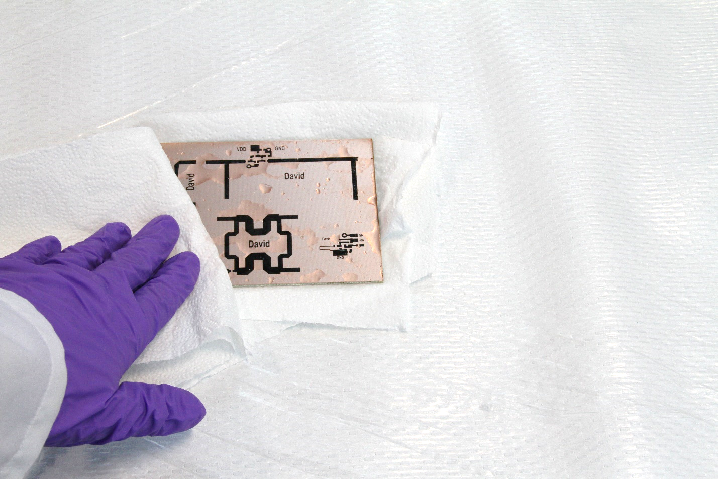
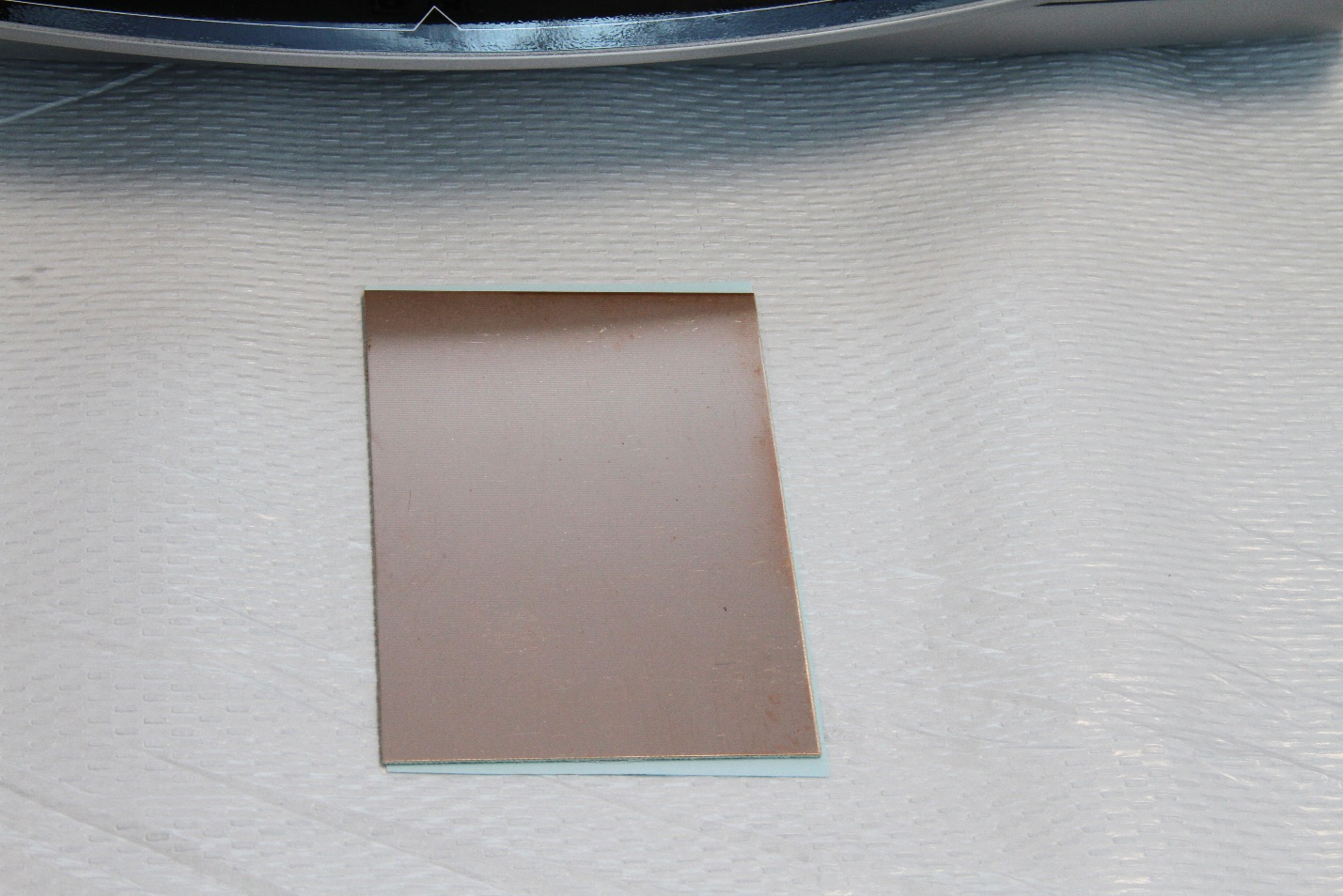
Here is the resulting PCB. Note how the text is written correctly now. This was because the transfer process undoes the “flip” you did in layout (it creates the mirror image of the flipped layout).
The black layout is approx.. 55% styrene, which still has many holes in it. We will add another “filler” layer to fill those holes. This is a technique that is very useful for high-precision PCBs. Many hobbyiests will skip this step.
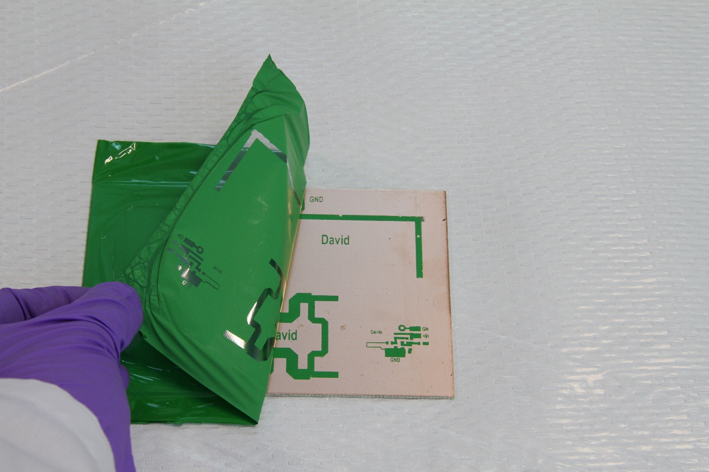
Place a piece of the green filler paper, flat side on the PCB, and wrap 2-3 cm of the foil around the front edge. This is to hold the foil as it enters the laminator.
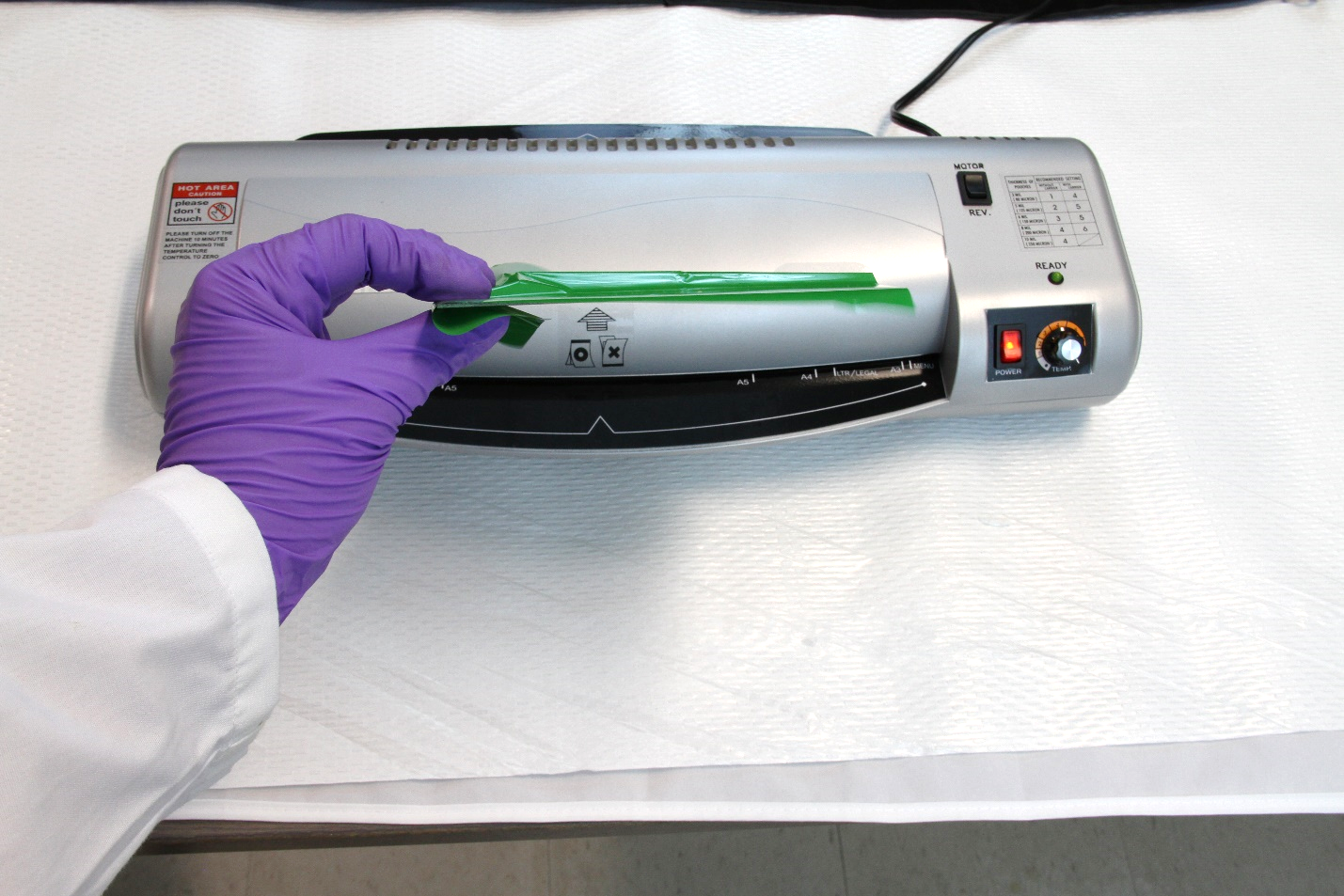
Pass the board through the laminator once. Holding the back edges fo the green sheet gently to remove wringles.
Pass a second time. Then smply peel off the green foil. Your finished board should look like this.
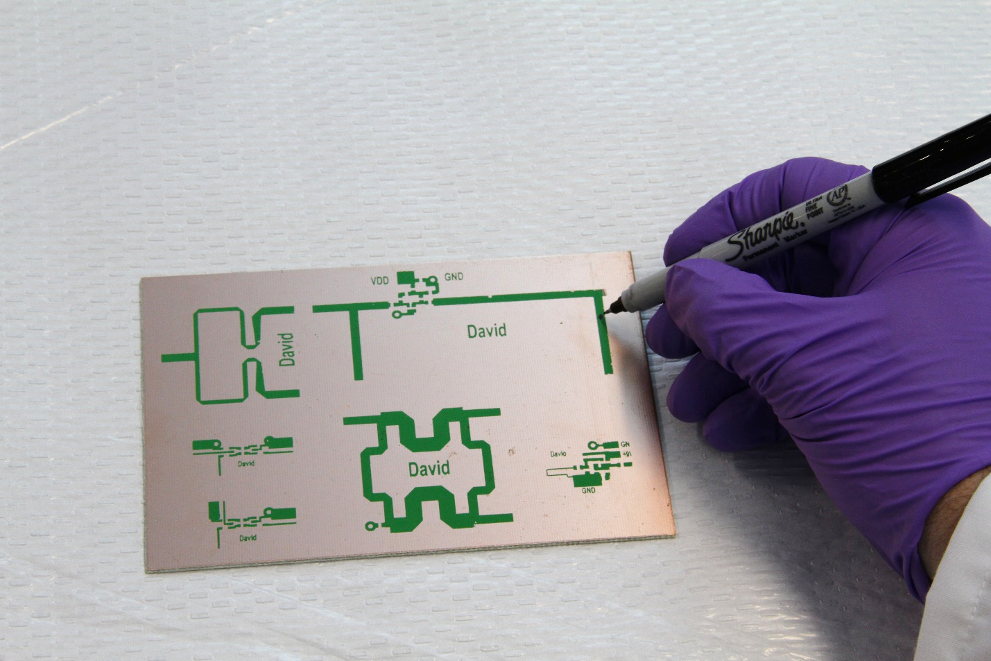
There are sometimes defects, either in the original black or in the foil. These can easily be filled with a Sharpie ® – a perminant, alchohol based marker. Other non-water soluable markers should work fine too. Simply draw over any areas that have defects.
Preparing PCB for Etching
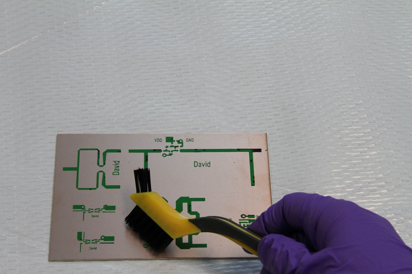
There may also be areas where the green foil is covering areas that it shouldn’t. A simply brush with a fine plastic brush will remove those areas. Note that once the green foil is down, the layout is robust, so brushing will not remove anything adheared to the original black toner.
If you place your PCB in an etchant now, the top layer would etch correctly, but the entire back ground plane would etch off too!!
We need to protect the back side so that it does not etch. This can be done in several ways. People have used nail polish, tape, even a very large Sharpie (anything that coats and is not water soluable). We use an alcohol based finish known as Shellac. It is named after the shellac beetle, whose crushed and dried skins are used for futurate polish. We use it as it is alcohol based, and thus non-water soluble and also easy to remove later with alcohol. In the US and Europe it is easy to obtain and inexpensive. You can buy it as a paint or you can make it from dired shellac pieces (sold on Amazon) and alcohol. The key attributes are: non-water soluble, quick-dry/easy to apply, can be removed after etching.
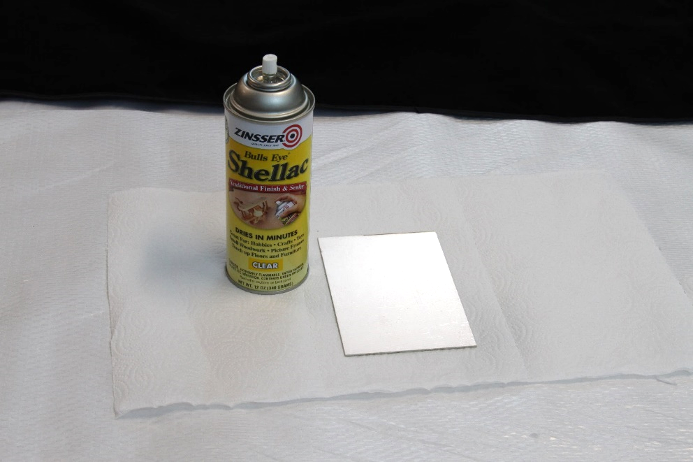
Place the PCB face down on an absorbent paper towel. This is an important step as the Shellac will tend to wick around the edges onto the front of the PCB if there is now towel. The towel will absorb any excess on the edges.
Spray a uniform coating on the board – make sure it covers the whole board, with now bubbles or missed areas. You can let it sit for 60 seconds to make sure any bubbles are gone and the area is covered. Below is an example of a fully coated back side.
After the Shellac has dried (10 min), you may begin the etching process.